Difference between revisions of "ADP-Forlinx Adapter Board Data Sheet"
Jump to navigation
Jump to search
| Line 23: | Line 23: | ||
'''[[VEYE-MIPI-IMX385 Starlight Camera|VEYE-MIPI-IMX385]]''' | '''[[VEYE-MIPI-IMX385 Starlight Camera|VEYE-MIPI-IMX385]]''' | ||
|} | |} | ||
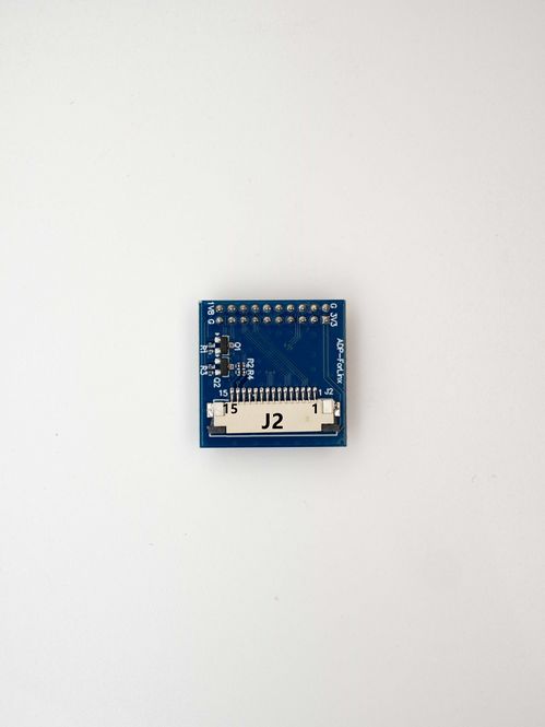
| − | [[File:ADP- | + | [[File:ADP-Forlinx pinlist 02.jpg|alt=ADP-Forlinx Pinlist|thumb|665x665px|ADP-Forlinx Pinlist]] |
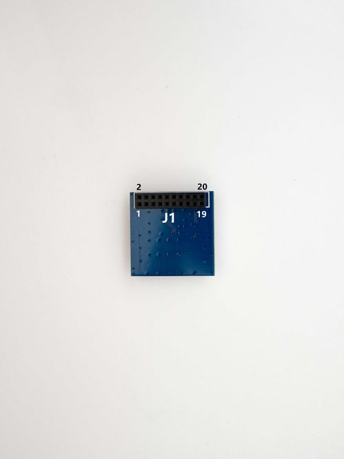
| − | [[File:ADP- | + | [[File:ADP-Forlinx pinlist 01.jpg|alt=ADP-Forlinx pinlist|thumb|665x665px|ADP-Forlinx pinlist]] |
==Board Pinlist 引脚说明== | ==Board Pinlist 引脚说明== | ||
{| class="wikitable" | {| class="wikitable" | ||
| − | | colspan="3" |''' | + | | colspan="3" |'''J1:Connect to Forlinx OKMX8MPX-C V2.0 Camera Interface''' |
| − | |||
|- | |- | ||
|'''Pin NO. 引脚号''' | |'''Pin NO. 引脚号''' | ||
| Line 37: | Line 36: | ||
|- | |- | ||
|1 | |1 | ||
| − | | | + | |VCC3V3 |
| − | | | + | |PWR OUT |
|- | |- | ||
|2 | |2 | ||
| − | | | + | |GND |
| − | | | + | | |
|- | |- | ||
|3 | |3 | ||
| − | | | + | |NC |
| − | | | + | | |
|- | |- | ||
|4 | |4 | ||
| Line 53: | Line 52: | ||
|- | |- | ||
|5 | |5 | ||
| − | | | + | |MIPI_CK_N |
| | | | ||
|- | |- | ||
|6 | |6 | ||
| − | | | + | |MIPI_CK_P |
| | | | ||
|- | |- | ||
| Line 73: | Line 72: | ||
|- | |- | ||
|10 | |10 | ||
| − | | | + | |NC |
| | | | ||
|- | |- | ||
|11 | |11 | ||
| − | | | + | |NC |
| | | | ||
|- | |- | ||
|12 | |12 | ||
| − | | | + | |GND |
| | | | ||
|- | |- | ||
|13 | |13 | ||
| − | | | + | |MIPI_L0_P |
| | | | ||
|- | |- | ||
|14 | |14 | ||
| − | | | + | |MIPI_L0_N |
| | | | ||
|- | |- | ||
|15 | |15 | ||
| − | | | + | |MIPI_L1_P |
| | | | ||
|- | |- | ||
|16 | |16 | ||
| − | | | + | |MIPI_L1_N |
| | | | ||
|- | |- | ||
|17 | |17 | ||
| − | | | + | |SDA_1.8V |
| | | | ||
|- | |- | ||
|18 | |18 | ||
| − | | | + | |SCL_1.8V |
| | | | ||
|- | |- | ||
| Line 113: | Line 112: | ||
|- | |- | ||
|20 | |20 | ||
| − | | | + | |VDD1V8 |
| − | |||
| − | |||
| − | |||
| − | |||
| − | |||
| − | |||
| − | |||
| − | |||
| − | |||
| − | |||
| − | |||
| − | |||
| | | | ||
| − | |||
| − | |||
| − | |||
| − | |||
| − | |||
| − | |||
| − | |||
| − | |||
| − | |||
| − | |||
| − | |||
| − | |||
| − | |||
| − | |||
| − | |||
| − | |||
| − | |||
| − | |||
| − | |||
| − | |||
| − | |||
| − | |||
| − | |||
| − | |||
| − | |||
| − | |||
| − | |||
| − | |||
|} | |} | ||
| − | |||
{| class="wikitable" | {| class="wikitable" | ||
| − | | colspan=" | + | | colspan="3" |'''J2:TOP contact,connect with VEYE camera module''' |
| − | ''' | + | '''J2:上接触,与VEYE系列模组互联''' |
|- | |- | ||
| − | |||
| − | |||
| − | |||
|'''Pin NO. 引脚号''' | |'''Pin NO. 引脚号''' | ||
|'''NAME 名称''' | |'''NAME 名称''' | ||
| Line 169: | Line 124: | ||
|- | |- | ||
|1 | |1 | ||
| − | |||
| − | |||
| − | |||
|GND | |GND | ||
| | | | ||
|- | |- | ||
| − | + | |2 | |
| − | + | |MIPI_L0_N | |
| − | |||
| − | |||
| − | |||
| − | |||
| − | |||
| − | |||
| − | |||
| − | |||
| − | |||
| − | |||
| − | |||
| − | |||
| − | |||
| − | |||
| − | |||
| − | |||
| − | |||
| − | |||
| − | |||
| − | |||
| − | |||
| − | |||
| − | |||
| − | |||
| − | |||
| − | |||
| − | |||
| − | |||
| − | |||
| − | |||
| − | |||
| − | |||
| − | |||
| − | |||
| − | |||
| − | |||
| − | |||
| − | |||
| − | |||
| − | |||
| − | |||
| − | |||
| − | |||
| − | | 2 | ||
| − | | | ||
| | | | ||
|- | |- | ||
|3 | |3 | ||
| − | | | + | |MIPI_L0_P |
| − | |||
| − | |||
| − | |||
| − | |||
| − | |||
| − | |||
| − | |||
| − | |||
| − | |||
| − | |||
| − | |||
| − | |||
| − | |||
| − | |||
| − | |||
| − | |||
| − | |||
| − | |||
| − | |||
| − | |||
| − | |||
| − | |||
| − | |||
| − | |||
| | | | ||
| − | |||
| − | |||
| − | |||
| − | |||
| − | |||
| − | |||
| − | |||
| − | |||
| − | |||
| − | |||
| − | |||
| − | |||
| − | |||
| − | |||
| − | |||
| − | |||
| − | |||
| − | |||
| − | |||
| − | |||
| − | |||
| − | |||
| − | |||
| − | |||
| − | |||
| − | |||
| − | |||
| − | |||
| − | |||
| − | |||
|- | |- | ||
|4 | |4 | ||
| − | |||
| − | |||
| − | |||
| − | |||
| − | |||
| − | |||
| − | |||
| − | |||
| GND | | GND | ||
| | | | ||
|- | |- | ||
| − | | | + | |5 |
| − | |||
| − | |||
| − | |||
| − | |||
| − | |||
| − | |||
| − | |||
| − | |||
| − | |||
| − | |||
| − | |||
| − | |||
| − | |||
| − | |||
| − | |||
| − | |||
| − | |||
| − | |||
| − | |||
| − | |||
|MIPI_L1_N | |MIPI_L1_N | ||
| − | |||
| − | |||
| − | |||
| − | |||
| − | |||
| − | |||
| − | |||
| − | |||
| − | |||
| − | |||
| − | |||
| − | |||
| − | |||
| − | |||
| − | |||
| − | |||
| − | |||
| − | |||
| − | |||
| − | |||
| − | |||
| − | |||
| − | |||
| − | |||
| − | |||
| − | |||
| − | |||
| − | |||
| − | |||
| − | |||
| − | |||
| − | |||
| − | |||
| − | |||
| − | |||
| − | |||
| − | |||
| − | |||
| − | |||
| − | |||
| − | |||
| − | |||
| − | |||
| − | |||
| | | | ||
| − | |||
| − | |||
| − | |||
| − | |||
| − | |||
| − | |||
| − | |||
| − | |||
| − | |||
| − | |||
| − | |||
| − | |||
| − | |||
| − | |||
| − | |||
| − | |||
| − | |||
| − | |||
| − | |||
| − | |||
| − | |||
| − | |||
| − | |||
| − | |||
| − | |||
| − | |||
| − | |||
| − | |||
| − | |||
| − | |||
| − | |||
| − | |||
| − | |||
| − | |||
| − | |||
| − | |||
| − | |||
| − | |||
| − | |||
| − | |||
| − | |||
| − | |||
| − | |||
| − | |||
| − | |||
| − | |||
| − | |||
| − | |||
| − | |||
| − | |||
| − | |||
| − | |||
| − | |||
| − | |||
| − | |||
| − | |||
| − | |||
|- | |- | ||
|6 | |6 | ||
| − | | | + | |MIPI_L1_P |
| | | | ||
|- | |- | ||
|7 | |7 | ||
| − | | | + | |GND |
| | | | ||
|- | |- | ||
| Line 432: | Line 156: | ||
|- | |- | ||
|9 | |9 | ||
| − | | | + | | MIPI_CK_P |
| | | | ||
|- | |- | ||
|10 | |10 | ||
| − | | | + | |GND |
| | | | ||
|- | |- | ||
|11 | |11 | ||
| − | | | + | |NC |
| | | | ||
|- | |- | ||
|12 | |12 | ||
| − | | | + | |NC |
| | | | ||
|- | |- | ||
|13 | |13 | ||
| − | | | + | |SCL |
| − | | | + | |3.3V LEVEL |
|- | |- | ||
|14 | |14 | ||
| − | | | + | |SDA |
| − | | | + | |3.3V LEVEL |
|- | |- | ||
|15 | |15 | ||
| − | | | + | |VCC3V3 |
| | | | ||
|} | |} | ||
| − | |||
==Schematic 原理图== | ==Schematic 原理图== | ||
| − | + | Download schematic file | |
==Board Dimension 尺寸图== | ==Board Dimension 尺寸图== | ||
| − | + | Download 2D DXF file | |
==PCBA 3D STP File(3D STP文件)== | ==PCBA 3D STP File(3D STP文件)== | ||
| − | + | Download 3D STP file | |
__FORCETOC__ | __FORCETOC__ | ||
Revision as of 15:24, 19 July 2023
Adapter Board:ADP-Forlinx DATA SHEET
转接板:ADP-Forlinx数据手册
1 Introduction 产品介绍
ADP-Forlinx是一款转接板,可将VEYE系列FFC接口转换为飞凌嵌入式20pin双排针插座接口(OKMX8MPX-C V2.0)。
ADP-Forlinx is an adapter board that can convert the FFC interfaces of VEYE series cameras to the Forlinx OKMX8MPX-C V2.0 20pin interface.
2 Product Picture 产品图片
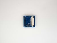
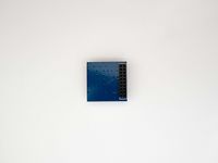
| PART NUMBER / 型号 | FRONT VIEW / 正面图片 | BACK VIEW / 背面图片 | Camera Support / 适配摄像机模组 |
| ADP-Forlinx | VEYE-MIPI-IMX327S |
3 Board Pinlist 引脚说明
| J1:Connect to Forlinx OKMX8MPX-C V2.0 Camera Interface | ||
| Pin NO. 引脚号 | NAME 名称 | Remarks 说明 |
| 1 | VCC3V3 | PWR OUT |
| 2 | GND | |
| 3 | NC | |
| 4 | NC | |
| 5 | MIPI_CK_N | |
| 6 | MIPI_CK_P | |
| 7 | NC | |
| 8 | NC | |
| 9 | NC | |
| 10 | NC | |
| 11 | NC | |
| 12 | GND | |
| 13 | MIPI_L0_P | |
| 14 | MIPI_L0_N | |
| 15 | MIPI_L1_P | |
| 16 | MIPI_L1_N | |
| 17 | SDA_1.8V | |
| 18 | SCL_1.8V | |
| 19 | GND | |
| 20 | VDD1V8 | |
| J2:TOP contact,connect with VEYE camera module
J2:上接触,与VEYE系列模组互联 | ||
| Pin NO. 引脚号 | NAME 名称 | Remarks 说明 |
| 1 | GND | |
| 2 | MIPI_L0_N | |
| 3 | MIPI_L0_P | |
| 4 | GND | |
| 5 | MIPI_L1_N | |
| 6 | MIPI_L1_P | |
| 7 | GND | |
| 8 | MIPI_CK_N | |
| 9 | MIPI_CK_P | |
| 10 | GND | |
| 11 | NC | |
| 12 | NC | |
| 13 | SCL | 3.3V LEVEL |
| 14 | SDA | 3.3V LEVEL |
| 15 | VCC3V3 | |
4 Schematic 原理图
Download schematic file
5 Board Dimension 尺寸图
Download 2D DXF file
6 PCBA 3D STP File(3D STP文件)
Download 3D STP file


