查看中文
CS-USB-IMX307 Data Sheet
1 Introduction
CS-USB-IMX307 is a cost-effective USB camera. This module use the SONY STARVIS CMOS image sensor IMX307LQD-C,built-in ISP processing.
Users can easily integrate into embedded systems or PC platforms via USB interface.
2 Features
- SONY IMX307 STARVIS Sensor, 1/2.8 inch 2 Mega
- Built-in ISP processing
- USB2.0 Interface,USB Video Class(UVC)
- Data fromat : YUY2 / MJPG / H.264
- Standard lens mount
- IR-CUT circuit
- BLC, Digtal WDR, 2D/3D noise reduction, Anti-fog
- Brightness, Contrast, Sharpness, Saturation adjustable
3 Thechnical Detail
| Technical Details
|
| SENSOR
|
| Sensor
|
SONY IMX307LQD-C STARVIS
|
| Pixels
|
2.07M pixels
|
| Resolution
|
1920*1080 MAX
|
| Image Size
|
Diagonal 6.46 mm (Type 1/2.8)
|
| Unit Cell Size
|
2.9um (H)*2.9um(V)
|
| SNR1s Value
|
0.24lx
|
| ISP
|
| YUY2 Frame Rate
|
640*360@25fps / 30fps
|
| MJPG Frame Rate
|
1920*1080@25fps / 30fps, 1280*720@50fps / 60fps, 640*360@25fps / 30fps
|
| H.264 Frame Rate
|
1920*1080@25fps / 30fps, 1280*720@50fps / 60fps, 640*360@25fps / 30fps
|
| Exposure
|
Auto or Manual
|
| White Balance
|
Auto or Manual
|
| Shutter
|
1/25(1/30)s to 1/20,000s
|
| Slow Shutter
|
Coming Soon
|
| Denoising
|
2D/3D noise reduction
|
| Image Setting
|
Brightness, Contrast, Sharpness, Saturation,Flip, Mirror
|
| Image Enhancement
|
BLC, Digtal WDR, Defog
|
| Day/Night Switch
|
Manual or IR-CUT filter with external trigger
|
| Lens & IR-CUT
|
| Lens
|
Support M12*0.5 or M16*0.5 depend on lens mount
|
| Lens Mount with IR-CUT
|
MTV12 or MTV16
|
| Mounting Hole
|
2 screw holes with diameter of 2.2mm,20mm Center-to-Center Spacing
|
| Interface
|
| Connector
|
MX1.25*4,USB2.0 Interface
|
| Communication Interface
|
USB2.0,UVC Protocol
|
| IR-CUT Control
|
IR-CUT motor control, 3.3VDC
|
| Day/Night External Trigger
|
3.3VDC to 5VDC compatibility
|
| General
|
| Operating Conditions
|
-10℃~60℃, Humidity 95% or less, non-condensing
|
| Power Supply
|
5VDC
|
| Power Consumption
|
5VDC,1.5W MAX
|
| Dimension
|
38mm*38mm*10mm(not include lens and lens mount)
|
4 Interface & Pin list
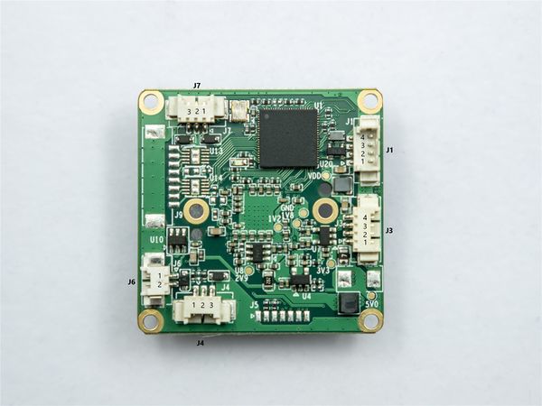
CS-USB-IMX307 BOTTOM INTERFACE
| J1:USB2.0 Interface
|
| Pin NO.
|
NAME
|
Remarks
|
| 1
|
VBUS(5V)
|
|
| 2
|
D-
|
|
| 3
|
D+
|
|
| 4
|
GND
|
|
| J3:Power Input, Used during firmware upgrade
|
| Pin NO.
|
NAME
|
Remarks
|
| 1
|
5VDC
|
5V IN
|
| 2
|
NC
|
|
| 3
|
NC
|
|
| 4
|
GND
|
|
| J4:Day/Night External Trigger
|
| Pin NO.
|
NAME
|
Remarks
|
| 1
|
IR LED ON
|
INPUT,ACTIVE LOW
|
| 2
|
GND
|
|
| 3
|
RESERVE
|
|
| J6:IRCUT Control
|
| Pin NO.
|
NAME
|
Remarks
|
| 1
|
IRCUT1
|
|
| 2
|
IRCUT2
|
|
| J6 IRCUT Control Functional specifications
|
| MODE
|
pin
|
Signal polarity
|
Image type
|
Filter position
|
| Mode 1
|
IRCUT1
|
+
|
color
|
Infrared cutoff
|
| IRCUT2
|
-
|
| Mode 2
|
IRCUT1
|
-
|
mono
|
Full wavelength pass
|
| IRCUT2
|
+
|
| J7:Configurable GPIO ( RESERVE )
|
| Pin NO.
|
NAME
|
Remarks
|
| 1
|
GPIO0
|
Can Be Configured
|
| 2
|
GND
|
|
| 3
|
GPIO1
|
Can Be Configured
|
5 Board Dimension
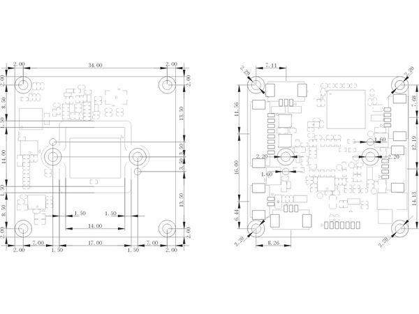
CS-USB-IMX307 CAD drawing / unit : mm
Download dwg file here


