查看中文
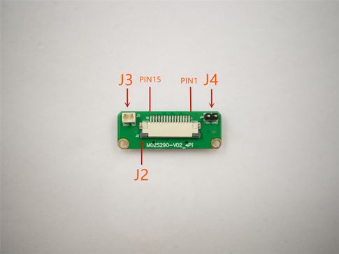
connector position(front)
Mini Adapter Board Description
1 Introduction
Mini Adapter Board connect the Raspberry Pi:
Connect J2 interface and CSI-2 interface on Raspberry Pi with 1.00mm15pin pitch FFC cable(TypeB).
2 Adapter Board Diagram, Layout
| 1
|
GND
|
| 2
|
MIPI_L0_N
|
| 3
|
MIPI_L0_P
|
| 4
|
GND
|
| 5
|
MIPI_L1_N
|
| 6
|
MIPI_L1_P
|
| 7
|
GND
|
| 8
|
MIPI_CK_N
|
| 9
|
MIPI_CK_P
|
| 10
|
GND
|
| 11
|
RESERVE, Not Connected
|
| 12
|
RESERVE, Not Connected
|
| 13
|
SCL_3.3V
|
| 14
|
SDA_3.3V
|
| 15
|
RESERVE, Not Connected
|
| 1
|
RESERVE, Not Connected
|
2
|
RESERVE, Not Connected
|
| 3
|
GND
|
4
|
RESERVE, Not Connected
|
| 5
|
RESERVE, Not Connected
|
6
|
RESERVE, Not Connected
|
| 7
|
RESERVE, Not Connected
|
8
|
RESERVE, Not Connected
|
| 9
|
GND
|
10
|
GND
|
| 11
|
RESERVE, Not Connected
|
12
|
RESERVE, Not Connected
|
| 13
|
RESERVE, Not Connected
|
14
|
RESERVE, Not Connected
|
| 15
|
GND
|
16
|
GND
|
| 17
|
MIPI_CK_P
|
18
|
SCL_3.3V
|
| 19
|
MIPI_CK_N
|
20
|
SDA_3.3V
|
| 21
|
GND
|
22
|
RESERVE, Not Connected
|
| 23
|
MIPI_L1_P
|
24
|
RESERVE, Not Connected
|
| 25
|
MIPI_L1_N
|
26
|
RESERVE, Not Connected
|
| 27
|
GND
|
28
|
RESERVE, Not Connected
|
| 29
|
MIPI_L0_P
|
30
|
RESERVE, Not Connected
|
| 31
|
MIPI_L0_N
|
32
|
RESERVE, Not Connected
|
| 33
|
GND
|
34
|
GND
|
| 35
|
GND
|
36
|
GND
|
| 37
|
VCC3V3
|
38
|
VCC3V3
|
| 39
|
VCC3V3
|
40
|
VCC3V3
|

