Difference between revisions of "ADP-N1 Adapter Board Data Sheet"
Jump to navigation
Jump to search
| (35 intermediate revisions by 3 users not shown) | |||
| Line 1: | Line 1: | ||
| − | + | <big><big><big>'''Adapter Board:ADP-N1 Data Sheet'''</big></big></big> | |
| − | + | <big>'''<u>**Discontinued Product,Replacement Part NO. [[ADP-N1-V2.0 Adapter Board Data Sheet|ADP-N1-V2.0]]</u>'''</big> | |
| + | |||
| + | <big>'''<u>**停产产品,替代型号[[ADP-N1-V2.0 Adapter Board Data Sheet|ADP-N1-V2.0]]</u>'''</big> | ||
| − | == | + | ==Product Introduction(产品介绍)== |
ADP-N1 is a camera interposer module for NVIDIA Jetson AGX Xavier & TX2 DevKit. | ADP-N1 is a camera interposer module for NVIDIA Jetson AGX Xavier & TX2 DevKit. | ||
| − | ==Product | + | ADP-N1是NVIDIA Jetson AGX Xavier和TX2开发套件的摄像头转接模块。 |
| + | |||
| + | ==Product Picture(产品图片)== | ||
{| class="wikitable" | {| class="wikitable" | ||
|'''PART NUMBER / 型号''' | |'''PART NUMBER / 型号''' | ||
| Line 17: | Line 21: | ||
|[[File:ADP-N1-T.jpg|alt=|center|thumb|200x200px|'''ADP-N1-T''']] | |[[File:ADP-N1-T.jpg|alt=|center|thumb|200x200px|'''ADP-N1-T''']] | ||
|[[File:ADP-N1-B.jpg|alt=|center|thumb|200x200px|'''ADP-N1-B''']] | |[[File:ADP-N1-B.jpg|alt=|center|thumb|200x200px|'''ADP-N1-B''']] | ||
| − | |[[File:FFC30-0.5-KH.jpg|alt=|center|thumb|200x200px|''' | + | |[[File:FFC30-0.5-KH.jpg|alt=|center|thumb|200x200px|'''FFC28P-0.5MM-20CM-T''']] |
|[[File:ADP-N1-6CAM 001.jpg|alt=|center|thumb|200x200px|'''SKETCH MAP''']] | |[[File:ADP-N1-6CAM 001.jpg|alt=|center|thumb|200x200px|'''SKETCH MAP''']] | ||
|} | |} | ||
| Line 23: | Line 27: | ||
[[File:ADP-N1-B-PinList.jpg|alt=|thumb|600x600px|ADP-N1 J7 PINLIST]] | [[File:ADP-N1-B-PinList.jpg|alt=|thumb|600x600px|ADP-N1 J7 PINLIST]] | ||
| − | ==Adapter Board | + | ==Adapter Board Pinlist(接口和引脚说明)== |
| + | {| class="wikitable" | ||
| + | | colspan="3" |'''J8:Funcation Jumper(功能选择)''' | ||
| + | |- | ||
| + | |'''<big>Pin NO.(引脚号)</big>''' | ||
| + | |'''<big>NAME(名称)</big>''' | ||
| + | |'''<big>Remarks(说明)</big>''' | ||
| + | |- | ||
| + | |1 | ||
| + | |CAM_VSYNC | ||
| + | |Internal Connect with J7-86 through a level shifter(3.3V to 1.8V) | ||
| + | |- | ||
| + | |2 | ||
| + | |COM | ||
| + | |Internal pull up to 3.3V, Rpu=1.5KΩ | ||
| + | |- | ||
| + | |3 | ||
| + | |Ext Trigger In | ||
| + | |Internal Connect with J9-1 | ||
| + | |} | ||
| + | {| class="wikitable" | ||
| + | | colspan="3" |'''J9''' | ||
| + | |- | ||
| + | |'''<big>Pin NO.(引脚号)</big>''' | ||
| + | |'''<big>NAME(名称)</big>''' | ||
| + | |'''<big>Remarks(说明)</big>''' | ||
| + | |- | ||
| + | |1 | ||
| + | |Ext Trigger In | ||
| + | |Internal Connect with J8-3 | ||
| + | |- | ||
| + | |2 | ||
| + | |GND | ||
| + | | | ||
| + | |- | ||
| + | |3 | ||
| + | |<big>NC</big> | ||
| + | | | ||
| + | |} | ||
| + | {| class="wikitable" | ||
| + | | colspan="2" |'''J8,J9,SW1 Functional specifications(J8,J9,SW1功能说明)''' | ||
| + | |- | ||
| + | |'''<big>J8 Jumper Status(J8跳选状态)</big>''' | ||
| + | |'''<big>Remarks(说明)</big>''' | ||
| + | |- | ||
| + | |Short connection J8-1 and J8-2 | ||
| + | (短接J8的1、2引脚) | ||
| + | |Select J7-86(CAM_VSYNC) as the trigger source,Only available Interconnect with TX2 platform | ||
| + | (与TX2/TX2平台主板互联时,此时选择的是J7-86(CAM_VSYNC)作为触发源) | ||
| + | |- | ||
| + | | rowspan="2" |Short connection J8-2 and J8-3 | ||
| + | (短接J8的2、3引脚) | ||
| + | |Select J9-1(Ext Trigger In) as the trigger source | ||
| + | (此时选择的是J9-1(Ext Trigger In)作为外触发源) | ||
| + | |- | ||
| + | |SW1 is used for testing to simulate an external trigger signal,Internal Connect with J9-3 | ||
| + | (此时SW1模拟一个外触发信号,与J9-3引脚连接在一起) | ||
| + | |} | ||
{| class="wikitable" | {| class="wikitable" | ||
| colspan="13" |'''J1 / J2 / J3 / J4 / J5 / J6''' | | colspan="13" |'''J1 / J2 / J3 / J4 / J5 / J6''' | ||
| Line 847: | Line 908: | ||
|} | |} | ||
| − | ==Adapter Board | + | ==Adapter Board Dimension(板子尺寸)== |
| − | [[File:ADP-N1-CAD2.jpg|alt=|thumb|600x600px|ADP-N1 CAD / unit:mm|none]][[ | + | [[File:ADP-N1-CAD2.jpg|alt=|thumb|600x600px|ADP-N1 CAD / unit:mm|none]][[Media:ADP-N1 DXF.zip|Download dwg file here]] |
__FORCETOC__ | __FORCETOC__ | ||
Latest revision as of 11:18, 19 August 2021
Adapter Board:ADP-N1 Data Sheet
**Discontinued Product,Replacement Part NO. ADP-N1-V2.0
**停产产品,替代型号ADP-N1-V2.0
1 Product Introduction(产品介绍)
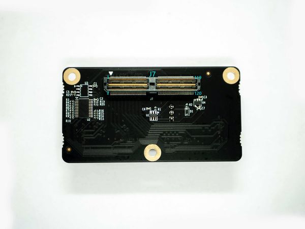
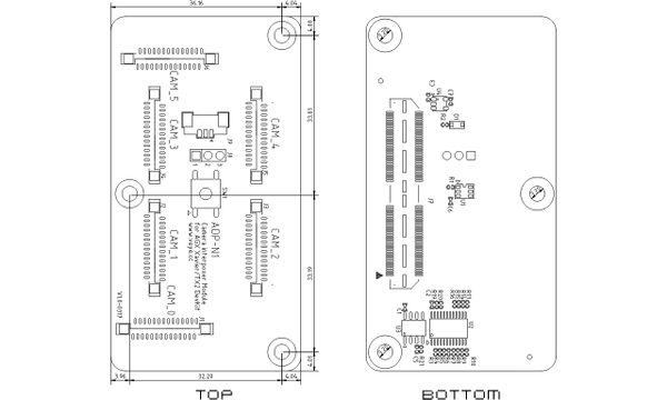
ADP-N1 is a camera interposer module for NVIDIA Jetson AGX Xavier & TX2 DevKit.
ADP-N1是NVIDIA Jetson AGX Xavier和TX2开发套件的摄像头转接模块。
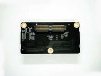
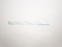
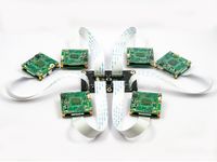
2 Product Picture(产品图片)
| PART NUMBER / 型号 | FRONT VIEW / 正面图片 | BACK VIEW / 背面图片 | FFC CABLE/FFC线缆 | SKETCH MAP/示意图 |
| ADP-N1 |
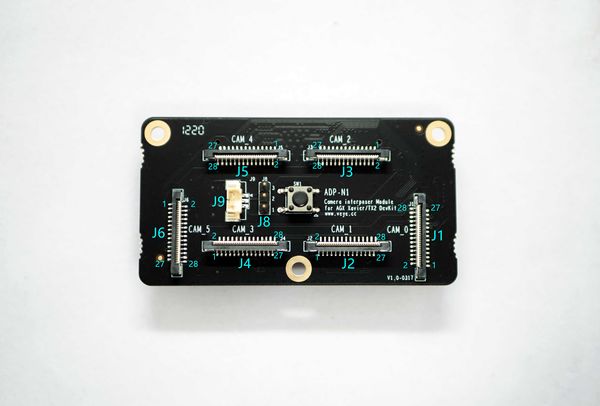
3 Adapter Board Pinlist(接口和引脚说明)
| J8:Funcation Jumper(功能选择) | ||
| Pin NO.(引脚号) | NAME(名称) | Remarks(说明) |
| 1 | CAM_VSYNC | Internal Connect with J7-86 through a level shifter(3.3V to 1.8V) |
| 2 | COM | Internal pull up to 3.3V, Rpu=1.5KΩ |
| 3 | Ext Trigger In | Internal Connect with J9-1 |
| J9 | ||
| Pin NO.(引脚号) | NAME(名称) | Remarks(说明) |
| 1 | Ext Trigger In | Internal Connect with J8-3 |
| 2 | GND | |
| 3 | NC | |
| J8,J9,SW1 Functional specifications(J8,J9,SW1功能说明) | |
| J8 Jumper Status(J8跳选状态) | Remarks(说明) |
| Short connection J8-1 and J8-2
(短接J8的1、2引脚) |
Select J7-86(CAM_VSYNC) as the trigger source,Only available Interconnect with TX2 platform
(与TX2/TX2平台主板互联时,此时选择的是J7-86(CAM_VSYNC)作为触发源) |
| Short connection J8-2 and J8-3
(短接J8的2、3引脚) |
Select J9-1(Ext Trigger In) as the trigger source
(此时选择的是J9-1(Ext Trigger In)作为外触发源) |
| SW1 is used for testing to simulate an external trigger signal,Internal Connect with J9-3
(此时SW1模拟一个外触发信号,与J9-3引脚连接在一起) | |
| J1 / J2 / J3 / J4 / J5 / J6 | ||||||||||||
| Pin NO. | J1 | J2 | J3 | J4 | J5 | J6 | ||||||
| NAME | Remarks | NAME | Remarks | NAME | Remarks | NAME | Remarks | NAME | Remarks | NAME | Remarks | |
| 1 | GND | GND | GND | GND | GND | GND | ||||||
| 2 | NC | NC | NC | NC | NC | NC | ||||||
| 3 | NC | NC | NC | NC | NC | NC | ||||||
| 4 | GND | GND | GND | GND | GND | GND | ||||||
| 5 | NC | NC | NC | NC | NC | NC | ||||||
| 6 | NC | NC | NC | NC | NC | NC | ||||||
| 7 | GND | GND | GND | GND | GND | GND | ||||||
| 8 | CSI_A_CLK_P | CSI_B_CLK_P | CSI_C_CLK_P | CSI_D_CLK_P | CSI_E_CLK_P | CSI_F_CLK_P | ||||||
| 9 | CSI_A_CLK_N | CSI_B_CLK_N | CSI_C_CLK_N | CSI_D_CLK_N | CSI_E_CLK_N | CSI_F_CLK_N | ||||||
| 10 | GND | GND | GND | GND | GND | GND | ||||||
| 11 | CSI_A_D1_P | CSI_B_D1_P | CSI_C_D1_P | CSI_D_D1_P | CSI_E_D1_P | CSI_F_D1_P | ||||||
| 12 | CSI_A_D1_N | CSI_B_D1_N | CSI_C_D1_N | CSI_D_D1_N | CSI_E_D1_N | CSI_F_D1_N | ||||||
| 13 | GND | GND | GND | GND | GND | GND | ||||||
| 14 | CSI_A_D0_P | CSI_B_D0_P | CSI_C_D0_P | CSI_D_D0_P | CSI_E_D0_P | CSI_F_D0_P | ||||||
| 15 | CSI_A_D0_N | CSI_B_D0_N | CSI_C_D0_N | CSI_D_D0_N | CSI_E_D0_N | CSI_F_D0_N | ||||||
| 16 | GND | GND | GND | GND | GND | GND | ||||||
| 17 | NC | NC | NC | NC | NC | NC | ||||||
| 18 | RESERVE | NC | RESERVE | NC | RESERVE | NC | RESERVE | NC | RESERVE | NC | RESERVE | NC |
| 19 | GND | GND | GND | GND | GND | GND | ||||||
| 20 | SCL0 | 3.3V Level | SCL1 | 3.3V Level | SCL2 | 3.3V Level | SCL3 | 3.3V Level | SCL4 | 3.3V Level | SCL5 | 3.3V Level |
| 21 | SDA0 | 3.3V Level | SDA1 | 3.3V Level | SDA2 | 3.3V Level | SDA3 | 3.3V Level | SDA4 | 3.3V Level | SDA5 | 3.3V Level |
| 22 | GND | GND | GND | GND | GND | GND | ||||||
| 23 | Sync0 | Sync0 | Sync0 | Sync0 | Sync0 | Sync0 | ||||||
| 24 | Sync1 | Sync1 | Sync1 | Sync1 | Sync1 | Sync1 | ||||||
| 25 | VDD_3V3_SLP | PWR OUT | VDD_3V3_SLP | PWR OUT | VDD_3V3_SLP | PWR OUT | VDD_3V3_SLP | PWR OUT | VDD_3V3_SLP | PWR OUT | VDD_3V3_SLP | PWR OUT |
| 26 | VDD_3V3_SLP | PWR OUT | VDD_3V3_SLP | PWR OUT | VDD_3V3_SLP | PWR OUT | VDD_3V3_SLP | PWR OUT | VDD_3V3_SLP | PWR OUT | VDD_3V3_SLP | PWR OUT |
| 27 | VDD_3V3_SLP | PWR OUT | VDD_3V3_SLP | PWR OUT | VDD_3V3_SLP | PWR OUT | VDD_3V3_SLP | PWR OUT | VDD_3V3_SLP | PWR OUT | VDD_3V3_SLP | PWR OUT |
| 28 | GND | GND | GND | GND | GND | GND | ||||||
| J7 | |||||||||||
| Pin NO. | NAME | Remarks | Pin NO. | NAME | Remarks | Pin NO. | NAME | Remarks | Pin NO. | NAME | Remarks |
| 1 | CSI_A_D0_P | 31 | CSI_C_D1_P | 61 | NC | 91 | NC | ||||
| 2 | CSI_B_D0_P | 32 | CSI_D_D1_P | 62 | NC | 92 | NC | ||||
| 3 | CSI_A_D0_N | 33 | CSI_C_D1_N | 63 | NC | 93 | NC | ||||
| 4 | CSI_B_D0_N | 34 | CSI_D_D1_N | 64 | NC | 94 | NC | ||||
| 5 | GND | 35 | GND | 65 | NC | 95 | NC | ||||
| 6 | GND | 36 | GND | 66 | NC | 96 | NC | ||||
| 7 | CSI_A_CLK_P | 37 | CSI_E_D0_P | 67 | NC | 97 | NC | ||||
| 8 | CSI_B_CLK_P | 38 | CSI_F_D0_P | 68 | NC | 98 | NC | ||||
| 9 | CSI_A_CLK_N | 39 | CSI_E_D0_N | 69 | GND | 99 | GND | ||||
| 10 | CSI_B_CLK_N | 40 | CSI_F_D0_N | 70 | GND | 100 | GND | ||||
| 11 | GND | 41 | GND | 71 | NC | 101 | NC | ||||
| 12 | GND | 42 | GND | 72 | NC | 102 | NC | ||||
| 13 | CSI_A_D1_P | 43 | CSI_E_CLK_P | 73 | NC | 103 | NC | ||||
| 14 | CSI_B_D1_P | 44 | CSI_F_CLK_P | 74 | NC | 104 | NC | ||||
| 15 | CSI_A_D1_N | 45 | CSI_E_CLK_N | 75 | CAM_I2C_SCL | 1.8V Level | 105 | NC | |||
| 16 | CSI_B_D1_N | 46 | CSI_F_CLK_N | 76 | NC | 106 | NC | ||||
| 17 | GND | 47 | GND | 77 | CAM_I2C_SDA | 1.8V Level | 107 | NC | |||
| 18 | GND | 48 | GND | 78 | NC | 108 | VDD_3V3_SLP | PWR | |||
| 19 | CSI_C_D0_P | 49 | CSI_E_D1_P | 79 | GND | 109 | VDD_5V0_IO_SYS | PWR | |||
| 20 | CSI_D_D0_P | 50 | CSI_F_D1_P | 80 | GND | 110 | VDD_3V3_SLP | PWR | |||
| 21 | CSI_C_D0_N | 51 | CSI_E_D1_N | 81 | NC | 111 | NC | ||||
| 22 | CSI_D_D0_N | 52 | CSI_F_D1_N | 82 | NC | 112 | NC | ||||
| 23 | GND | 53 | GND | 83 | NC | 113 | NC | ||||
| 24 | GND | 54 | GND | 84 | VDD_3V3_SLP | PWR | 114 | NC | |||
| 25 | CSI_C_CLK_P | 55 | NC | 85 | NC | 115 | GND | ||||
| 26 | CSI_D_CLK_P | 56 | NC | 86 | CAM_VSYNC | RESERVE | 116 | GND | |||
| 27 | CSI_C_CLK_N | 57 | NC | 87 | NC | 117 | NC | ||||
| 28 | CSI_D_CLK_N | 58 | NC | 88 | NC | 118 | VDD_5V0_IO_SYS | PWR | |||
| 29 | GND | 59 | NC | 89 | NC | 119 | NC | ||||
| 30 | GND | 60 | NC | 90 | NC | 120 | VDD_5V0_IO_SYS | PWR | |||

