Difference between revisions of "CS-MIPI-SC132 Data Sheet"
Jump to navigation
Jump to search
| (32 intermediate revisions by 3 users not shown) | |||
| Line 4: | Line 4: | ||
==Introduction== | ==Introduction== | ||
| − | CS-MIPI-SC132 is a cost-effective CSI-2 (MIPI) interface camera module that uses the SC132GS global shutter MONO CMOS sensor whice is [http://www.smartsenstech.com/siteweien/enindex.html SmartSens Technology]‘s SmartGS™ series. CS-MIPI-SC132 supports trigger mode and video stream mode. | + | CS-MIPI-SC132 / CS-MIPI-SC132-V2 is a cost-effective CSI-2 (MIPI) interface camera module that uses the SC132GS global shutter MONO CMOS sensor whice is [http://www.smartsenstech.com/siteweien/enindex.html SmartSens Technology]‘s SmartGS™ series. CS-MIPI-SC132 / CS-MIPI-SC132-V2 supports trigger mode and video stream mode. |
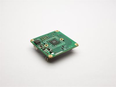
| − | [[File:CS-MIPI-SC132 | + | [[File:CS-MIPI-SC132-N001.jpg|alt=|thumb|400x400px|CS-MIPI-SC132 TOP]] |
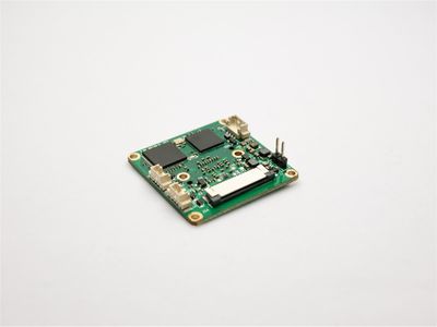
| − | [[File:CS-MIPI-SC132 | + | [[File:CS-MIPI-SC132-N002.jpg|alt=|thumb|400x400px|CS-MIPI-SC132 BOTTOM]] |
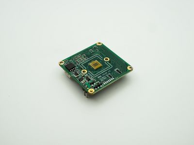
| + | [[File:CS-MIPI-SC132-V2.0 01.jpg|alt=|thumb|400x400px|CS-MIPI-SC132-V2 TOP]] | ||
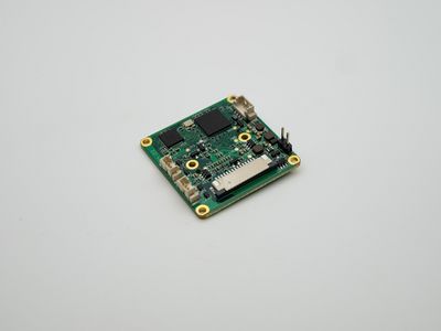
| + | [[File:CS-MIPI-SC132-V2.0 02.jpg|alt=|thumb|400x400px|CS-MIPI-SC132-V2 BOTTOM]] | ||
| + | |||
==Features== | ==Features== | ||
| − | *1/4 inch 1.3m pixel | + | *1/4 inch 1.3m pixel SmartGS<sup>®</sup> CMOS sensor |
*Only mono mode is supported | *Only mono mode is supported | ||
*Global shutter | *Global shutter | ||
| Line 20: | Line 23: | ||
*Support trigger mode | *Support trigger mode | ||
*Firmware upgrade via USB flash drive | *Firmware upgrade via USB flash drive | ||
| − | *Support Raspberry PI Platform | + | *Support Raspberry PI Platform, NVIDIA JETSON Platform |
==Technical Detail== | ==Technical Detail== | ||
| Line 29: | Line 32: | ||
|- | |- | ||
|Sensor | |Sensor | ||
| − | |SmartSens | + | |SmartSens SmartGS<sup>®</sup> [https://smartsens.oss-cn-beijing.aliyuncs.com/web/products/SC132GS_V5.0.pdf SC132GS] |
|- | |- | ||
|Pixels | |Pixels | ||
| Line 52: | Line 55: | ||
|- | |- | ||
|Frame Rate | |Frame Rate | ||
| − | |1280*1080@ | + | |1280*1080@max45fps,1280*720@max60fps, 640*480@max120fps |
| − | 1080*1280@ | + | 1080*1280@max45fps, 720*1280@max60fps, 480*640@max120fps |
|- | |- | ||
|Exposure | |Exposure | ||
| Line 73: | Line 76: | ||
|- | |- | ||
|Soft Trigger | |Soft Trigger | ||
| − | | | + | |The image is triggered by the DRA(Direct Register Access) |
| − | |||
| − | |||
| − | |||
|- | |- | ||
|Hardware Trigger | |Hardware Trigger | ||
| − | |The image is triggered by an external trigger | + | |The image is triggered by an external trigger signal,Support multi-camera synchronization |
|- | |- | ||
| colspan="2" |'''Lens''' | | colspan="2" |'''Lens''' | ||
| Line 107: | Line 107: | ||
|- | |- | ||
|MIPI Data bandwidth | |MIPI Data bandwidth | ||
| − | |594Mbps / lane | + | |594Mbps / lane * 2 |
|- | |- | ||
|Data Type | |Data Type | ||
| Line 120: | Line 120: | ||
|- | |- | ||
|Power Supply | |Power Supply | ||
| − | |<u>5VDC / 3.3VDC</u> | + | |<u>[[Power supply mode switching|5VDC / 3.3VDC]]</u> optional,3.3V default |
|- | |- | ||
|Power Consumption | |Power Consumption | ||
| − | | | + | |CS-MIPI-SC132:Rate Power 1.16W |
| + | / CS-MIPI-SC132-V2:Rate Power 1.23W,Transient Power 1.32W | ||
|- | |- | ||
|Dimension | |Dimension | ||
| − | |38mm*38mm* | + | |38mm*38mm*12mm(not include lens and lens mount) |
|} | |} | ||
==Optical Quantum Efficiency== | ==Optical Quantum Efficiency== | ||
| Line 137: | Line 138: | ||
|} | |} | ||
==Interface & Pin list== | ==Interface & Pin list== | ||
| − | [[File:CS-MIPI-SC132 002.jpg|alt=|thumb| | + | [[File:CS-MIPI-SC132 002.jpg|alt=CS-MIPI-SC132-TOP LAYER|thumb|600x600px|CS-MIPI-SC132-TOP LAYER]] |
| − | [[File:CS-MIPI-SC132 | + | [[File:CS-MIPI-SC132-N04 IF.jpg|alt=|thumb|600x600px|CS-MIPI-SC132-BOTTOM LAYER]] |
| + | [[File:CS-MIPI-SC132-V2.0 04.jpg|alt=CS-MIPI-SC132-V2-TOP LAYER|thumb|600x600px|CS-MIPI-SC132-V2-TOP LAYER]] | ||
| + | [[File:CS-MIPI-SC132-V2.0 03.jpg|alt=CS-MIPI-SC132-V2-BOTTOM LAYER|thumb|600x600px|CS-MIPI-SC132-V2-BOTTOM LAYER]] | ||
{| class="wikitable" | {| class="wikitable" | ||
| colspan="3" |'''J1 : Firmware Update''' | | colspan="3" |'''J1 : Firmware Update''' | ||
| Line 168: | Line 171: | ||
|1 | |1 | ||
|VCC5V | |VCC5V | ||
| − | | | + | |Optional power supply. [[Power supply mode switching|<u>How to use 5V power supply</u>]] |
|- | |- | ||
|2 | |2 | ||
| Line 175: | Line 178: | ||
|} | |} | ||
{| class="wikitable" | {| class="wikitable" | ||
| − | | colspan="3" |'''J7 : | + | | colspan="3" |'''J7 : GPIO''' |
|- | |- | ||
|'''Pin NO.''' | |'''Pin NO.''' | ||
| Line 182: | Line 185: | ||
|- | |- | ||
|1 | |1 | ||
| − | | | + | |Trigger In |
| − | | | + | |Compatible with 2.5-3.3V level |
|- | |- | ||
|2 | |2 | ||
| Line 190: | Line 193: | ||
|- | |- | ||
|3 | |3 | ||
| − | | | + | |Strobe Out |
| − | | | + | |2.5V level |
| + | |} | ||
| + | {| class="wikitable" | ||
| + | | colspan="3" |'''J14 : UART''' | ||
| + | |- | ||
| + | |'''Pin NO.''' | ||
| + | |'''NAME''' | ||
| + | |'''Remarks''' | ||
| + | |- | ||
| + | |1 | ||
| + | |UART_TX | ||
| + | | | ||
| + | |- | ||
| + | |2 | ||
| + | |GND | ||
| + | | | ||
| + | |- | ||
| + | |3 | ||
| + | |UART_RX | ||
| + | | | ||
|} | |} | ||
{| class="wikitable" | {| class="wikitable" | ||
| Line 258: | Line 280: | ||
|15 | |15 | ||
|VCC3V3 | |VCC3V3 | ||
| − | | | + | |Use by default,[[Power supply mode switching|<u>How to use 5V power supply</u>]] |
|} | |} | ||
| + | |||
==Board Dimension== | ==Board Dimension== | ||
| − | [[File:CS-MIPI-SC132 CAD.jpg|alt=|none|thumb|600x600px|CS-MIPI-SC132 CAD FILE / unit:mm]] | + | [[File:CS-MIPI-SC132 CAD new.jpg|alt=|none|thumb|600x600px|CS-MIPI-SC132 CAD FILE / unit:mm]] |
| − | [[Media:CS-MIPI-SC132 CAD | + | [[File:CS-MIPI-SC132-V21-1213-2D.jpeg|alt=|none|thumb|600x600px|CS-MIPI-SC132-V2 CAD FILE / unit:mm]] |
| + | |||
| + | [[Media:CS-MIPI-SC132 CAD v2.dxf.zip|Download CS-MIPI-SC132 dxf file here]] | ||
| + | |||
| + | [[Media:CS-MIPI-SC132-V21-1213-2D.7z|Download CS-MIPI-SC132-V2 dxf file here]] | ||
| + | |||
| + | == PCBA 3D STP File == | ||
| + | [[Media:3D CS-MIPI-SC132.zip|Download CS-MIPI-SC132 3D STP file]] | ||
| + | |||
| + | [[Media:CS-MIPI-SC132-V21-1213-3D.7z|Download CS-MIPI-SC132-V2 3D STP file]] | ||
| + | ==Assembly Direction== | ||
| + | [[File:CS-MIPI-SC132-N003-dir.png|alt=CS-MIPI-SC132 002-dir|left|thumb|800x800px|CS-MIPI-SC132 002-dir]] | ||
Latest revision as of 14:39, 16 April 2023
CS-MIPI-SC132 Data Sheet
1 Introduction
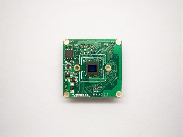
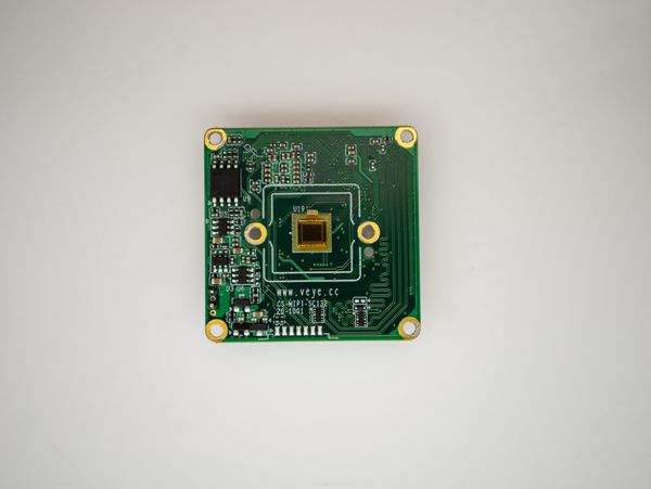
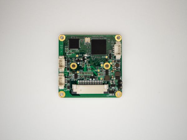
CS-MIPI-SC132 / CS-MIPI-SC132-V2 is a cost-effective CSI-2 (MIPI) interface camera module that uses the SC132GS global shutter MONO CMOS sensor whice is SmartSens Technology‘s SmartGS™ series. CS-MIPI-SC132 / CS-MIPI-SC132-V2 supports trigger mode and video stream mode.
2 Features
- 1/4 inch 1.3m pixel SmartGS® CMOS sensor
- Only mono mode is supported
- Global shutter
- Built-in ISP image processing
- CSI-2 data interface
- Uncompressed UYVY data format, YUV422-8bit data type
- Standard lens interface
- Brightness and contrast can be adjusted
- Support video stream mode
- Support trigger mode
- Firmware upgrade via USB flash drive
- Support Raspberry PI Platform, NVIDIA JETSON Platform
3 Technical Detail
| Technical Details | |
| SENSOR | |
| Sensor | SmartSens SmartGS® SC132GS |
| Pixels | 1.3M pixels |
| Resolution | 1080H*1280V |
| Image Size | 1/4" |
| Unit Cell Size | 2.7um *2.7um |
| Output Format | RAW MONO |
| Shutter Type | Global shutter |
| ISP | |
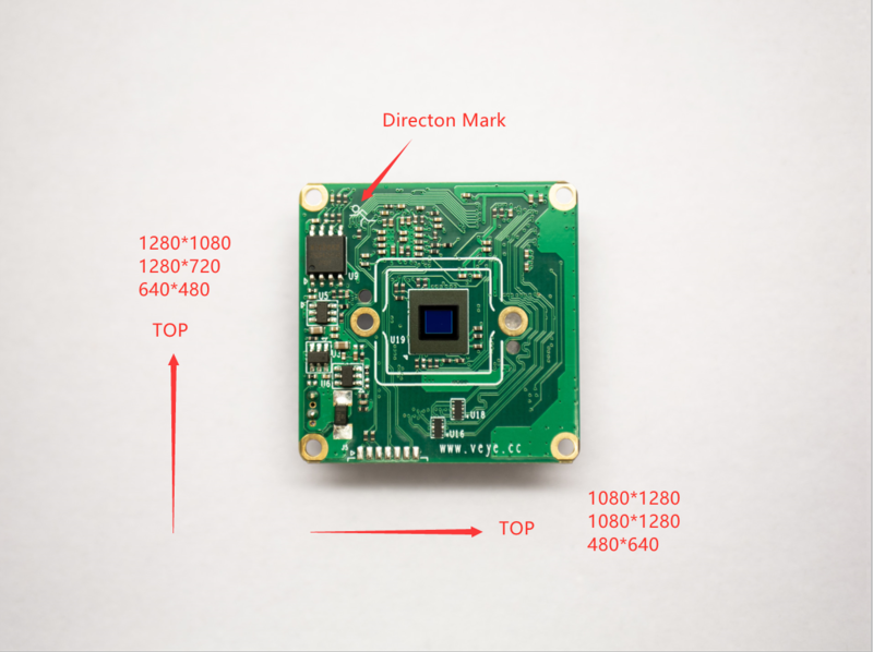
| Frame Rate | 1280*1080@max45fps,1280*720@max60fps, 640*480@max120fps
1080*1280@max45fps, 720*1280@max60fps, 480*640@max120fps |
| Exposure | Auto or Manual |
| Gain | Auto or Manual |
| Shutter | ( 0 - 1 / Frame Rate ) second |
| Image Setting | Brightness, Contrast, Gamma, Flip, Mirror |
| Image Synchronization mode | |
| Free-Run | The sensor runs under an autonomous clock system |
| Soft Trigger | The image is triggered by the DRA(Direct Register Access) |
| Hardware Trigger | The image is triggered by an external trigger signal,Support multi-camera synchronization |
| Lens | |
| Lens | MTV12 / MTV16 / CS |
| Lens Mount | M12*P0.5 / M16*P0.5 / CS |
| Mounting Hole | 2 screw holes with diameter of 2.2mm,20mm Center-to-Center Spacing |
| Interface | |
| Connector | 15PIN FPC, Compatible with Raspberry PI,JETSON NANO |
| Communication Interface | IIC, 3.3VDC |
| Video Data Interface | CSI-2 : 2 Data Lane,MIPI CSI-2 DC Specifications |
| MIPI CLK frequence | 297MHz |
| MIPI Data bandwidth | 594Mbps / lane * 2 |
| Data Type | YUV422-8bit |
| General | |
| Operating Conditions
(Bare PCB) |
Performance guarantee temperature:-20℃~60℃, Humidity 95% or less, non-condensing
Operating guarantee temperature: -30℃~85℃, Humidity 95% or less, non-condensing |
| Power Supply | 5VDC / 3.3VDC optional,3.3V default |
| Power Consumption | CS-MIPI-SC132:Rate Power 1.16W
/ CS-MIPI-SC132-V2:Rate Power 1.23W,Transient Power 1.32W |
| Dimension | 38mm*38mm*12mm(not include lens and lens mount) |
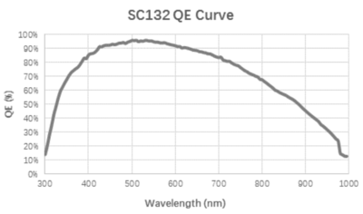
4 Optical Quantum Efficiency
| Sensor | Quantum Efficiency |
| SC132GS |
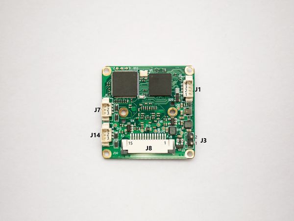
5 Interface & Pin list
| J1 : Firmware Update | ||
| Pin NO. | NAME | Remarks |
| 1 | VBUS(5V) | Connect the USB upgrade cable & USB disk |
| 2 | D- | |
| 3 | D+ | |
| 4 | GND | |
| J3 : Power Input | ||
| Pin NO. | NAME | Remarks |
| 1 | VCC5V | Optional power supply. How to use 5V power supply |
| 2 | GND | |
| J7 : GPIO | ||
| Pin NO. | NAME | Remarks |
| 1 | Trigger In | Compatible with 2.5-3.3V level |
| 2 | GND | |
| 3 | Strobe Out | 2.5V level |
| J14 : UART | ||
| Pin NO. | NAME | Remarks |
| 1 | UART_TX | |
| 2 | GND | |
| 3 | UART_RX | |
| J8 : CSI-2 Interface | ||
| Pin NO. | NAME | Remarks |
| 1 | GND | |
| 2 | MIPI_L0_N | |
| 3 | MIPI_L0_P | |
| 4 | GND | |
| 5 | MIPI_L1_N | |
| 6 | MIPI_L1_P | |
| 7 | GND | |
| 8 | MIPI_CK_N | |
| 9 | MIPI_CK_P | |
| 10 | GND | |
| 11 | NC | |
| 12 | NC | |
| 13 | SCL | 3.3V Level |
| 14 | SDA | 3.3V Level |
| 15 | VCC3V3 | Use by default,How to use 5V power supply |
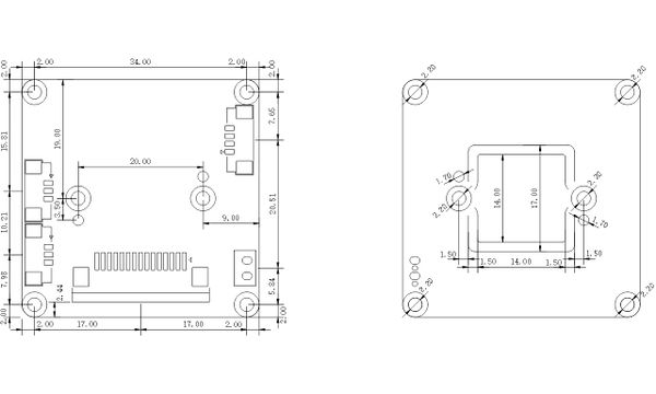
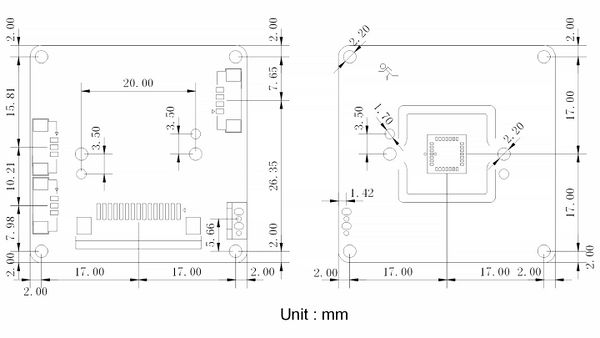
6 Board Dimension
Download CS-MIPI-SC132 dxf file here
Download CS-MIPI-SC132-V2 dxf file here
7 PCBA 3D STP File
Download CS-MIPI-SC132 3D STP file
Download CS-MIPI-SC132-V2 3D STP file
