Difference between revisions of "VEYE-MIPI-290/327 for Raspberry Pi"
| Line 18: | Line 18: | ||
'''Setup guide''' | '''Setup guide''' | ||
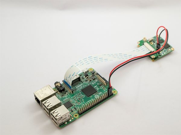
| − | *Connect the VEYE Camera Module the CSI-2 port using FFC | + | *Connect the VEYE Camera Module the CSI-2 port using FFC Cable('''type B'''). |
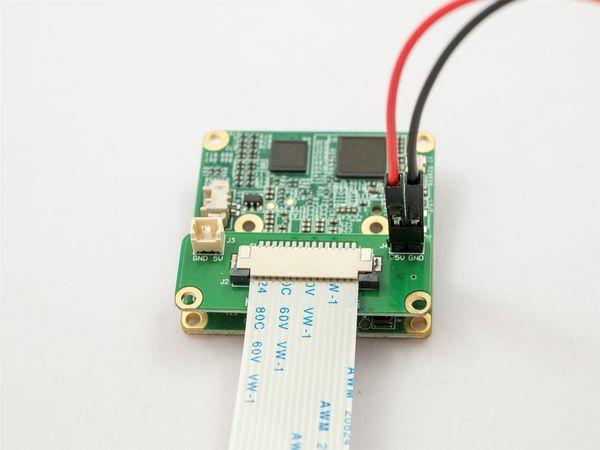
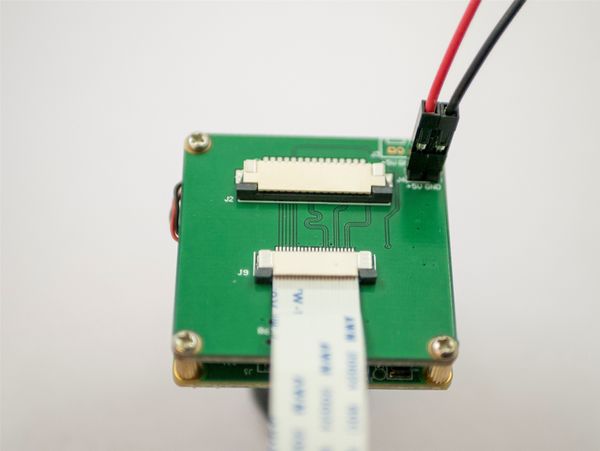
*Connect Dupont Line as shown below. VEYE-MIPI-290/327 need an addtional power. | *Connect Dupont Line as shown below. VEYE-MIPI-290/327 need an addtional power. | ||
*Startup RaspberryPi. | *Startup RaspberryPi. | ||
| Line 90: | Line 90: | ||
On Raspberry Pi, I2C-0 is used by GPU. We use I2C-1 as control bus for VEYE Camera Module. We provide a Shell Script — camera_i2c_config— to config pin usage. | On Raspberry Pi, I2C-0 is used by GPU. We use I2C-1 as control bus for VEYE Camera Module. We provide a Shell Script — camera_i2c_config— to config pin usage. | ||
| − | Video Control Toolkits Manual : [[ | + | Video Control Toolkits Manual : [[VEYE-MIPI-290/327 i2c/zh|VEYE-MIPI-290/327 i2c]] |
<br /> | <br /> | ||
===RPI Computer Module and RPI Zero Additional Info=== | ===RPI Computer Module and RPI Zero Additional Info=== | ||
| − | === FFC Cable Remarks === | + | ==== Overview ==== |
| + | RPI CM and Zero have a different MIPI CSI-2 port with standard RPI. And CM has can support dual cameras. Here I use a VEYE-MIPI-290/327 and a RPI CM3 as an example. | ||
| + | |||
| + | PS: I use a Computer Module IO Board Plus designed by [http://www.waveshare.net/ WAVESHARE ELECTRONICS]. The official CMIO Board is similar. | ||
| + | |||
| + | ==== Hardware Setup ==== | ||
| + | |||
| + | ===== Connecting Video Stream Port ===== | ||
| + | |||
| + | *Connect the VEYE Camera Module the CSI-2 port using FFC Cable('''type A'''). | ||
| + | *Connect Dupont Line as shown below. VEYE-MIPI-290/327 need an addtional power. | ||
| + | *CM3 can support dual cameras. | ||
| + | |||
| + | ===== Connecting I2C to CMIO ===== | ||
| + | |||
| + | *CAM1: | ||
| + | |||
| + | Attach CD1_SDA to GPIO2 . | ||
| + | |||
| + | Attach CD1_SCL to GPIO3 . | ||
| + | |||
| + | *CAM0: | ||
| + | |||
| + | Attach CD0_SDA to GPIO44 . | ||
| + | |||
| + | Attach CD0_SCL to GPIO45 . | ||
| + | |||
| + | For RPI official CMIO board, please refer to [https://www.raspberrypi.org/documentation/hardware/computemodule/cmio-camera.md Link]. | ||
| + | |||
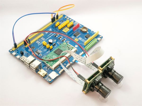
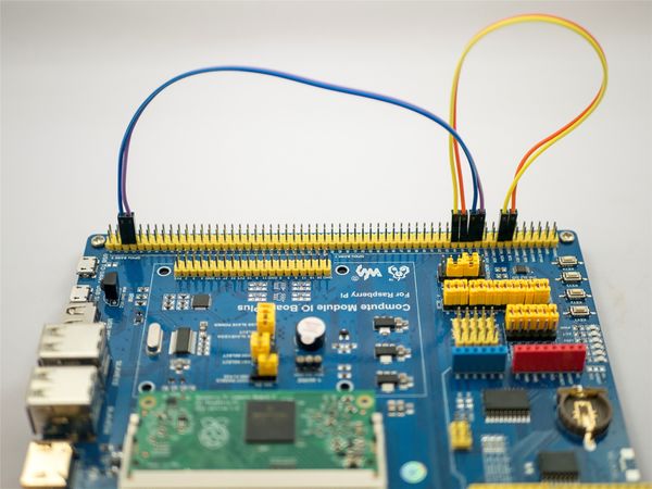
| + | For WAVESHARE CMIO board, as shown below. | ||
| + | [[File:Veye-computer module.jpg|center|thumb|600x600px|RPI CM2 to dual VEYE modules]] | ||
| + | |||
| + | |||
| + | [[File:Veye computermodule Wiring scheme00.jpg|center|thumb|600x600px|RPI CM2 to dual VEYE modules(Part1)]] | ||
| + | [[File:Veye computer moduleWiring scheme01.jpg|center|thumb|600x600px|RPI CM2 to dual VEYE modules(Part2)]] | ||
| + | <br /> | ||
| + | |||
| + | ==== System Setup and Configuration ==== | ||
| + | |||
| + | ==== Video Stream Toolkits ==== | ||
| + | |||
| + | ==== Video Control Toolkits ==== | ||
| + | <br /> | ||
| + | ===FFC Cable Remarks=== | ||
<br /> | <br /> | ||
Revision as of 17:41, 1 August 2019
This document is a work in progress.
How to Use Veye Mipi Camera with Raspberry Pi
1 Introduction
VEYE-MIPI-290/327 is a is a special camera module which is compatible with RASPBERRY PI. She use SONY STARVIS sensor——IMX290/IMX327 and has excellent ISP functions build-in.The output format is stanard UYVY stream. It is very easy to use it with RASPBERRY PI.Of course, she also has some subtle differences with the official version. She only support 1080p resolution,and i2c cmd is different.
Theoretically,VEYE Camera Modules support all Raspberry Pi. For performance reasons, I recommend you use 3,3+,4 version. This article uses Raspberry Pi 3B as an example to explain how the VEYE-MIPI-290/327 camera module working with Raspberry Pi. It also explain the specials of RPI Computer Module and Zero using VEYE Camera Module.
2 Hardware Setup
Essentials You Need:
- Raspberry PI Items : RPI, Network, MicroSD Card, Power, Monitor
- Camera Module Items : VEYE-MIPI-290/327, FFC,Dupont Line,Lens,Adaptor Board. (We developed 2 types of adaptor boards, Mini Adaptor Board and Adaptor Board. Mini board only support Standard RPI,Adaptor Board support both Standard RPI and CM & Zero.)
Setup guide
- Connect the VEYE Camera Module the CSI-2 port using FFC Cable(type B).
- Connect Dupont Line as shown below. VEYE-MIPI-290/327 need an addtional power.
- Startup RaspberryPi.
3 RaspberryPi System Setup and Configuration
- Setup RasapberryPi System,reference this link.
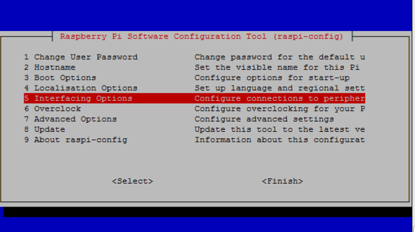
- Go to the main menu and open the Raspberry Pi Configuration tool. Enable Camera and I2C interface.
sudo raspi-config
- Enable SSH and Samba services.
4 Sofware Toolkits Install
4.1 Toolkits downloading
There are two way to install software toolkits.
- 1. Clone from github
git clone https://github.com/veyeimaging/raspberrypi
- 2. Downloading from github (link here), upload to RPI using samba or USB disk.
4.2 Toolkits Overview
- Software toolkits contains two parts. veye_raspcam is Video Stream Toolkits, i2c_cmd is Video Control Toolkits.
- Video Stream Tookkits provides real-time display, capture, video recording, etc.
- Video Control Toolkits is a shell script which provides ISP parameters configuration capbility.
- Both is Open Source.
5 Video Stream Toolkits Manual
VS toolkits provides several ELF file.
- veye_raspipreview
./veye_raspipreview -t 20000
Privew,20s video Real-time display to HDMI output.
./veye_raspipreview -t -1
If t is -1, Show continuous Real-time display to HDMI output.
- veye_raspivid
./veye_raspivid -t 5000 -o ~/test.h264
Implement H.264 format encoding and record for 5 seconds,Record the stream data to file ~/test.h264.
- veye_raspividyuv
./veye_raspividyuv -t 200 -o /dev/shm/test.yuv
Record UYVY data to file /dev/shm/ directory(which is in DDR), time is 200ms.
- veye_raspiraw
./veye_raspiraw -md 2 -t 200 -o /dev/shm/out.%04d.yuv
Record one UYVY data to file /dev/shm/ directory(which is in DDR).
- veye_raspistill
Capture a image and save it as jpeg file.DEVELOPING.
6 Video Control Toolkits Manual
On Raspberry Pi, I2C-0 is used by GPU. We use I2C-1 as control bus for VEYE Camera Module. We provide a Shell Script — camera_i2c_config— to config pin usage.
Video Control Toolkits Manual : VEYE-MIPI-290/327 i2c
7 RPI Computer Module and RPI Zero Additional Info
7.1 Overview
RPI CM and Zero have a different MIPI CSI-2 port with standard RPI. And CM has can support dual cameras. Here I use a VEYE-MIPI-290/327 and a RPI CM3 as an example.
PS: I use a Computer Module IO Board Plus designed by WAVESHARE ELECTRONICS. The official CMIO Board is similar.
7.2 Hardware Setup
7.2.1 Connecting Video Stream Port
- Connect the VEYE Camera Module the CSI-2 port using FFC Cable(type A).
- Connect Dupont Line as shown below. VEYE-MIPI-290/327 need an addtional power.
- CM3 can support dual cameras.
7.2.2 Connecting I2C to CMIO
- CAM1:
Attach CD1_SDA to GPIO2 .
Attach CD1_SCL to GPIO3 .
- CAM0:
Attach CD0_SDA to GPIO44 .
Attach CD0_SCL to GPIO45 .
For RPI official CMIO board, please refer to Link.
For WAVESHARE CMIO board, as shown below.
7.3 System Setup and Configuration
7.4 Video Stream Toolkits
7.5 Video Control Toolkits
8 FFC Cable Remarks
