Difference between revisions of "Camera module Stream Mode manual"
| Line 13: | Line 13: | ||
In this mode, the exposure parameters of the camera module can be configured manually or automatically. | In this mode, the exposure parameters of the camera module can be configured manually or automatically. | ||
===Hardware connection of sync mode=== | ===Hardware connection of sync mode=== | ||
| − | According to the following config method, J7-1 is used as the XVS signal and J7-2 as the XHS signal. | + | According to the following config method, J7-1 is used as the XVS signal and J7-2 as the XHS signal.(note: In version LV3.3, XHS signals no longer need to be connected) |
XVS time sequence diagram:[[File:XVS Timeing.png|alt=XVS time sequence diagram|center|thumb|800x800px|XVS timing sequence diagram]] | XVS time sequence diagram:[[File:XVS Timeing.png|alt=XVS time sequence diagram|center|thumb|800x800px|XVS timing sequence diagram]] | ||
====The method of connecting two cameras==== | ====The method of connecting two cameras==== | ||
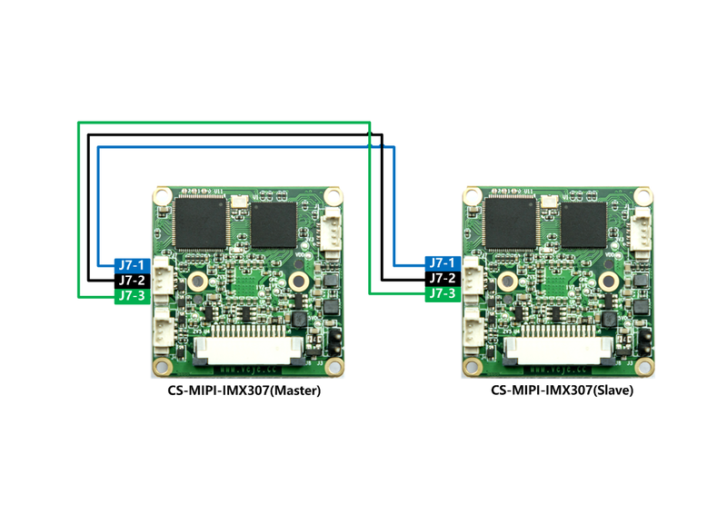
| − | [[File:CS-MIPI-IMX307双模组同步示意图.png|alt=CS-MIPI-IMX307双模组同步示意图|thumb|800x800px|CS-MIPI-IMX307 2 cameras sync mode |center]] | + | [[File:CS-MIPI-IMX307双模组同步示意图.png|alt=CS-MIPI-IMX307双模组同步示意图|thumb|800x800px|CS-MIPI-IMX307 2 cameras sync mode(note: In version LV3.3, XHS signals no longer need to be connected) |center]] |
=====Jetson nano B01 config===== | =====Jetson nano B01 config===== | ||
Reference link:[[CS-MIPI-X i2c/zh|cs_mipi_i2c.sh usage]] | Reference link:[[CS-MIPI-X i2c/zh|cs_mipi_i2c.sh usage]] | ||
Revision as of 09:45, 19 March 2021
1 Applicable Product models
CS-MIPI-IMX307
2 The concept of image synchronization mode
2.1 free running
In this mode, the camera module runs on its own.
2.2 stream sync mode
One camera module is configured in master mode, and the other camera modules are configured in slave mode.
The camera module in master mode outputs XVS and XHS signals, while the camera module in slave mode follows the master module for exposure and output data.
In this mode, the exposure parameters of the camera module can be configured manually or automatically.
3 Hardware connection of sync mode
According to the following config method, J7-1 is used as the XVS signal and J7-2 as the XHS signal.(note: In version LV3.3, XHS signals no longer need to be connected)
XVS time sequence diagram:
3.1 The method of connecting two cameras
3.1.1 Jetson nano B01 config
Reference link:cs_mipi_i2c.sh usage
- set cam0 as master
./cs_mipi_i2c.sh -w -f streammode -p1 1 -p2 0 -b 7
- set cam1 as slave
./cs_mipi_i2c.sh -w -f streammode -p1 1 -p2 1 -b 8
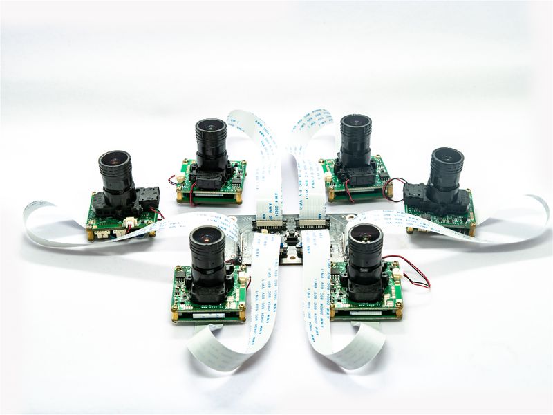
3.2 Jetson TX2/Xavier 6 cameras sync mode connection and configration
3.2.1 Jetson TX2/Xavier config
Reference link:cs_mipi_i2c.sh usage
- set cam0 as master
./cs_mipi_i2c.sh -w -f streammode -p1 1 -p2 0 -b 30
- set other 5 cameras as slave
./cs_mipi_i2c.sh -w -f streammode -p1 1 -p2 1 -b 31
./cs_mipi_i2c.sh -w -f streammode -p1 1 -p2 1 -b 32
./cs_mipi_i2c.sh -w -f streammode -p1 1 -p2 1 -b 33
./cs_mipi_i2c.sh -w -f streammode -p1 1 -p2 1 -b 34
./cs_mipi_i2c.sh -w -f streammode -p1 1 -p2 1 -b 35


