Mv mipi camera manual
MV series MIPI image module manual
1 Overview
MV series is a series of camera modules specially designed for machine vision. It is excellent in performance, compact and affordable in price. In addition to the video streaming mode, a trigger mode and a series of functions related to triggering are also provided. Provides a better option for embedded systems for machine vision applications.
To facilitate rapid development, we provide hardware datasheet , register manuals and drivers for embedded platforms, demos.
This article focuses on the functional principles of the MV camera in detail. For hardware manuals, registers, configuration scripts, drivers for different embedded platforms and usage, please refer to the corresponding documents.
In this article, the [Related Commands] column after each function lists the commands in the mv_mipi_i2c.sh script that are related to this function.
2 Image Acquisition
2.1 Rolling shutter and Global shutter
2.1.1 Rolling shutter
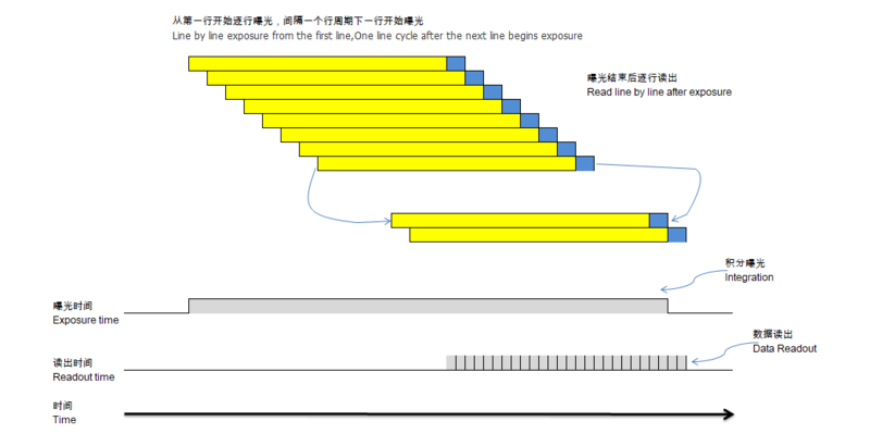
The rolling shutter sensor is implemented as shown in the figure below.。The exposure starts from the first line and the second line is exposed only after one line cycle.And so on, after N-1 rows the Nth row is exposed.It takes one cycle time to read out a row of data after the first row is exposed.After the first line is completely read out, the second line just starts to be read out. In this order, the whole image is completely read out. The rolling shutter sensors are less technically difficult than global exposure sensors, cheaper, and have greater resolution, making them a good choice for some static or slow object photography.
2.1.2 Global shutter
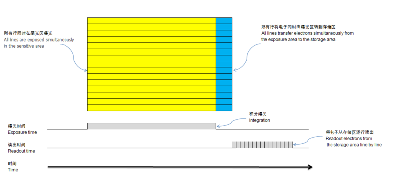
The global shutter sensor implementation is shown in the figure below. All rows of the sensor start exposure at the same time and end exposure at the same time. At the end of the exposure, the sensor transfers all electrons from the sensing area to the storage area and then reads out the pixel data row by row.The advantage of such exposure is that the image will not be shifted and skewed when shooting moving objects.
2.2 Start/Stop Acquisition
You can send the start acquisition and stop acquisition commands to the camera at any time.
Once the camera receives the start acquisition command, if working in video streaming mode, it will immediately start exposure and output images; if working in trigger mode, it will enter the state of waiting for the trigger signal. At the same time, the camera enters the running state.
Once the camera receives the stop acquisition command, it will complete the currently transmitting frames to ensure frame integrity, and then stop outputting images and enter the standby state. Note that the triggering process will be interrupted if triggering multiple frames is set and not all image frames have been output yet. That is, stopping the acquisition operation only guarantees the integrity of the current frame, not the entire trigger cycle.
Related commands :imgacq.
2.3 Video streaming mode
In video streaming mode, the camera continuously exposes and outputs images according to the configured ROI region and frame rate. It is recommended to get the maximum frame rate supported by the maxfps function after changing the ROI.
Related commands :trgmode,roi,fps,maxfps.
2.4 Normal trigger mode
2.4.1 Rolling shutter
For a rolling shutter sensor, such as IMX178, a complete image frame requires two image cycles to complete the process from exposure to output. So the maximum frame rate is half of the video streaming mode.
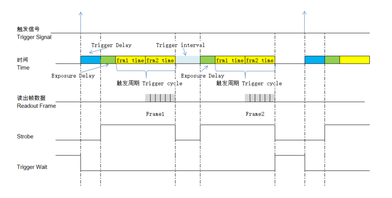
In normal trigger mode, for rolling shutter sensor, we refer to two consecutive frame cycles as one trigger cycle.
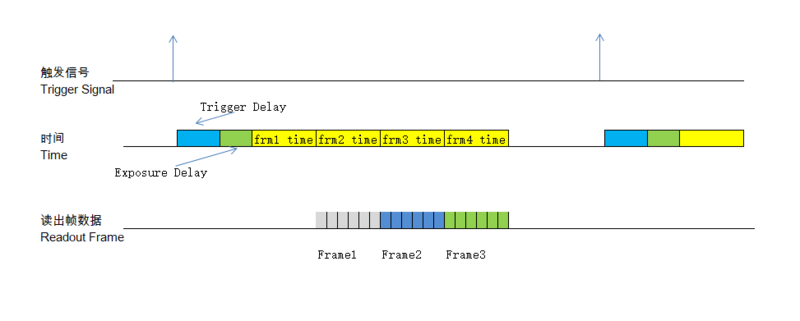
In normal trigger mode, if multiple frames are triggered at one time, the trigger delay acts after this trigger signal, and the trigger interval and exposure delay are valid before each trigger cycle.
The following figure shows an example of a trigger period with Trigger Number set to 2:
2.4.2 Global shutter
TODO
2.5 High-speed continuous trigger mode
2.5.1 Rolling shutter
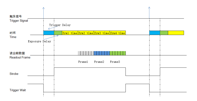
In high-speed trigger mode, assume Trigger Number is N, frames 2 to N are output immediately after the previous frame and there is no more trigger interval. This allows the same maximum frame rate to be achieved as in video streaming mode.
The following figure shows an example of a trigger period with Trigger Number set to 3:
2.6 Switching of modes
The working mode cannot be switched during operation; you must stop the acquisition before switch to a new working mode.
2.7 Trigger source
The soft trigger and hard trigger are only different in the source of trigger signal. The trigger delay, exposure delay, trigger frame number, trigger interval configurations and functions are exactly the same.
Related commands :trgsrc.
2.7.1 Software trigger mode
By writing 1 to the corresponding register of the camera via the i2c bus, a soft trigger is performed.
Since there is a certain delay in software processing and i2c transmission, the timeliness of soft trigger is worse than hard trigger , and hard trigger is recommended for the occasions with high timeliness requirements.
Related commands :trgone.
2.7.2 Hardware trigger mode
In hard trigger mode, the camera obtains the trigger signal by capturing the level change of the TrigIN IO. See the IO Control chapter for details.
2.8 Trigger statistics
The trigger statistics function counts the total number of triggers as well as the number of lost triggers.
Definition of total trigger number: in hard trigger mode, it is the number of triggers after trigger filtering; in soft trigger mode, it is the number of all triggers.
When the camera receives a trigger signal, it will not be able to respond to the new trigger signal if it is in the trigger cycle, which will cause the loss of the trigger signal.
Related commands :trgcount, trgclr.
3 Image Feature
3.1 Pixel Format
The output format of MV series cameras is compliant with the MIPI CSI-2 standard, and the supported pixel formats may vary from model to model. Refer to the following table.
| Model | Pixel Format | Note |
|---|---|---|
| MV-MIPI-IMX178M | Mono8,Mono10,Mono12 | sensor output data is always12bit-depth |
Related commands :fmtcap, pixelformat.
3.2 Image size and Max framerate
Image size depends on the sensor. It varies from model to model.
The maximum image frame rate depends on the sensor and the camera processing power, and the maximum frame rate varies for different image sizes.
After setting the completed image size (ROI area), the camera will automatically calculate the maximum frame rate and provide it to the user for reference.
The maximum frame rates for typical sizes are shown in the following table.
| model | size | max framerate | Note |
|---|---|---|---|
| MV-MIPI-IMX178M | 3088 × 2064 | 22.3 | Max size |
| 2592 x 1944 | 28.15 | ||
| 2560 x 2048 | 27 | ||
| 1920 x 1080 | 67 |
The actual frame rate can be less than the maximum frame rate and can be set to a decimal number.
To guarantee the camera frame rate, we specify that the maximum exposure time cannot be greater than [1/fps] seconds.
Related commands:maxwh,maxfps,fps。
3.3 ROI area
Only specific areas of the image can be transmitted by setting the camera's region of interest (ROI).
The parameters of the output region include the horizontal offset (x), vertical offset (y), width (w), and height (h) of the output region.
By default, the ROI area of the camera is the full resolution area of the sensor.
3.3.1 ROI parameter requirements
[x] ,[y], [height] must be 4-aligned and [width] must be 8-aligned.
| model | minimum ROI area | Note |
|---|---|---|
| MV-MIPI-IMX178M | 376 x 320 |
The camera will make necessary adjustments to the user parameters to meet the parameter requirements.
So it is highly recommended that you read out the actual ROI parameters after writing them.
Related commands:roi.
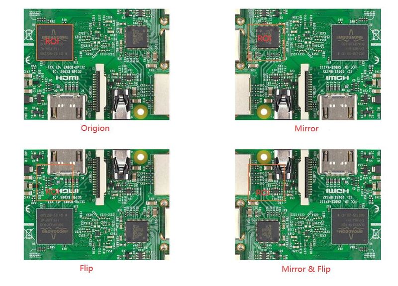
3.4 Mirror and Flip
This function is relatively easy to understand. A special note is that with both ROI and Mirror/Flip on, the image is first mirrored/flipped, and then ROI cropped.
Related commands:imgdir.
3.5 Blacklevel
Currently the application range of the black level value can only be selected for all pixels, and pixel selection is not supported. The lower the black level value, the darker the image is; the higher the black level value, the brighter the image is.
Related command: blacklevel.
3.6 Test Pattern
The following is an example of the test chart pattern in 12bit data format.
3.6.1 Mode 1: Grayscale gradient test pattern
The value of the first column is 0, and the grayscale value increases by 4 for each column to the right.
3.6.2 Mode 2: Vertical stripe test chart
The pixels in each column are FFEh/555h/AAAh/001h in order.
Related command: testimg.
4 ISP
4.1 Exposure and Gain Control
4.1.1 AAROI
The camera counts the current image brightness within the AAROI region and uses it for auto exposure and auto gain calculations. By default, AAROI is not enabled, and the real statistical area in effect is the entire area of the output image, i.e., the ROI area.
The AAROI coordinates are relative coordinates within the ROI area. So the area must be smaller than the image ROI.
Related command: aaroi,aaroienable.
4.1.2 Exposure
The camera exposure time range is (0-1000000/fps)us. All parameters of exposure time are in microseconds. However, due to the properties of the sensor, the actual exposure time unit of the sensor is 1 line, can not be accurate to 1us.
In any mode, the actual current exposure time can be read with the exptime command.
Exposure control modes: ME, AE, AE once.
Related command: expmode,exptime.
4.1.2.1 Manual Exposure(ME)
Use a fixed exposure time.
Related command:expmode,metime。
4.1.2.2 Auto Exposure(AE)
Automatically adjusts the exposure time of the camera so that the average brightness in the AAROI reaches the target value.
This process continues all the time and therefore allows for rapid adaptation to changes in the environment light.
The target brightness value ranges from 0 to 255, independent of pixelformat.
Related command:expmode,aatarget, aemaxtime.
4.1.2.3 Auto Exposure once(AE once)
When the camera is set to AE once mode by the expmode command, the camera will make one auto exposure adjustment and turn off the auto adjustment after finishing the adjustment. If the adjustment cannot be made to the target brightness due to a mismatch between the environment brightness and the maximum exposure time, the adjustment will also stop after timeout.
Related command:expmode,aatarget, aemaxtime.
4.1.3 Gain
The gain range of the camera, depending on the sensor used. An increase in gain will lead to an increase in noise, it is recommended not to use too much gain.
| model | Range | Step |
|---|---|---|
| MV-MIPI-IMX178M | 0-48dB | 0.1dB |
4.1.3.1 Manual Gain(MG)
Use a fixed gain.
Related command:gainmode,mgain。
4.1.3.2 Auto Gain(AG)
4.1.3.3 Auto Gain once(AG once)
4.1.4 Other notes
1. When enabling AE and AG at the same time, the camera gives priority to the use of exposure time and minimizes the use of gain. Try to avoid the noise caused by gain.
2. aeag_run_once_save command execute AE&AG once operation and save the results to the camera as manual values.This is a function that is useful when the camera is installed.
5 IO Control
5.1 Input IO Configuration
Now there is only one input pin: TriggerIN_IO. The function is: input signal for hard trigger.
The active edge of the trigger signal can be configured via the Trigger Edge function.
Related commands :trgedge.
5.1.1 Trigger Filter
In order to suppress the interference in the external trigger signal, MV series cameras have external trigger filtering function, including low level filtering and high level filtering.
The function of low level filtering is to filter out the interference signal on the low level, and the function of high level filtering is to filter out the interference signal on the high level.
The range of the filtering window can be set to [1,1000000]us.
The following figure shows an example of enabling both low level filtering and high level filtering with a filtering time of 1ms:
Related commands :trgfilter_enable,trgfilter_time.
5.1.2 Trigger Delay
MV series cameras have a trigger delay function. The trigger delay time can be set to [1,1000000]us. It is in effect for both hard and soft triggers.
Related commands :trgdelay.
5.2 Output IO Configuration
MV series cameras now have 2 output signals, OUT_IO1 and OUT_IO2.
OUT_IO1 can be configured for Strobe and Userout functions.
OUT_IO2 can be configured for five functions, Strobe, Userout, TriggerWait, XVS and XHS.
Related commands: outio1_mode, outio2_mode.
5.2.1 Strobe
In this mode, the camera sends a trigger signal to activate the flash. Strobe signal is active high, and when the trigger signal is received, the strobe signal level is pulled up, and the pull-up time is the sum of the exposure delay and trigger cycle.
5.2.2 UserOut
In this mode users can set their own constant output level of the camera to do special processing, such as controlling the constant light source or an alarm device.
The output level can be set individually for different OUT_IO.
5.2.3 TriggerWait
The trigger wait signal indicates that the camera is now ready to respond to the trigger signal.
The camera's trigger wait signal can be used to optimize trigger image acquisition and can effectively avoid the problem of over-triggering.
5.2.3.1 Normal trigger mode(Rolling shutter)
The following figure lists the Strobe signal and the TriggerWait signal with the number of trigger frames set to 2 as an example.
5.2.3.2 High-speed trigger mode(Rolling shutter)
The following figure lists the Strobe signal and the TriggerWait signal with the number of trigger frames set to 3 as an example.
5.2.4 XVS
Output the XVS signal of the sensor.
5.2.5 XHS
Output the XVS signal of the sensor.
5.2.6 Pin Reverse
To facilitate camera IO configuration and connection, the MV Series cameras have an output pin level reversal feature.
Related commands :outio1_rvs,outio2_rvs.
5.3 Read pin status
All input and output IO pins can be read for their current status via the i2c bus.
Related commands :gpios_status.
