Difference between revisions of "MV-MIPI-IMX178M Data Sheet"
Jump to navigation
Jump to search
| (19 intermediate revisions by 3 users not shown) | |||
| Line 4: | Line 4: | ||
==Introduction== | ==Introduction== | ||
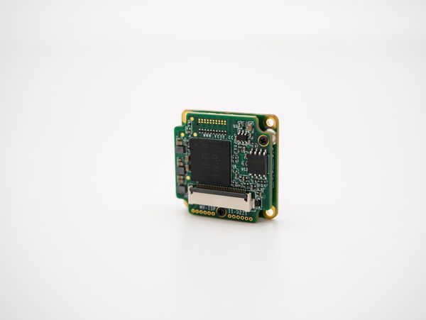
| − | MV-MIPI-IMX178M is a 6 million MONO industrial camera with MIPI interface. This camera has a small size (29*29mm) and rich functions, so it is suitable for integration as an image acquisition component. | + | MV-MIPI-IMX178M is a 6 million MONO industrial camera with MIPI interface. |
| + | |||
| + | This camera has a small size (29*29mm) and rich functions, so it is suitable for integration as an image acquisition component. | ||
[[File:MV-MIPI-IMX178M-F.jpg|alt=|thumb|'''MV-MIPI-IMX178M'''|600x600px]] | [[File:MV-MIPI-IMX178M-F.jpg|alt=|thumb|'''MV-MIPI-IMX178M'''|600x600px]] | ||
==Features== | ==Features== | ||
| − | * 1/1.8 6M Pixel SONY CMOS SENSOR | + | * 1/1.8<nowiki>''</nowiki> 6M Pixel SONY STARVIS CMOS SENSOR |
*MIPI CSI-2 Interface | *MIPI CSI-2 Interface | ||
| − | * | + | *RAW8、RAW10,RAW12 Data Format |
| − | *Video streaming mode(Free | + | *Video streaming mode(Free Running),Trigger mode,High-speed continuous trigger mode |
| − | * | + | *Hardware and Software trigger source |
| + | *Support trigger frame number, interval, delay, trigger filter function | ||
*Strobe synchronization | *Strobe synchronization | ||
| − | *ROI | + | *ROI |
*USER Output | *USER Output | ||
| + | *Flexible frame rate settings | ||
* | * | ||
| Line 25: | Line 29: | ||
| colspan="2" |'''Technical Details''' | | colspan="2" |'''Technical Details''' | ||
|- | |- | ||
| − | |Sensor | + | |Sensor Type |
|CMOS | |CMOS | ||
|- | |- | ||
| − | |Shutter | + | |Shutter Mode |
|Rolling Shutter | |Rolling Shutter | ||
|- | |- | ||
|Sensor | |Sensor | ||
| − | |SONY [https://www.sony-semicon. | + | |SONY [https://www.sony-semicon.com/files/62/pdf/p-12_IMX178LLJ_LQJ_Flyer.pdf IMX178LLJ-C] STARVIS |
|- | |- | ||
|Color | |Color | ||
| Line 38: | Line 42: | ||
|- | |- | ||
|Image Size | |Image Size | ||
| − | |1/1.8 | + | |1/1.8<nowiki>''</nowiki> |
|- | |- | ||
|Unit Cell Size | |Unit Cell Size | ||
| Line 44: | Line 48: | ||
|- | |- | ||
|Resolution | |Resolution | ||
| − | | | + | |3088(H) × 2064(V) |
|- | |- | ||
|Max Frame Rate | |Max Frame Rate | ||
| − | | | + | |3088×2064@40fps RAW8 |
| + | 3088×2064@39fps RAW10 | ||
| + | |||
| + | 3088×2064@33fps RAW12 | ||
|- | |- | ||
|Gain | |Gain | ||
| Line 65: | Line 72: | ||
|- | |- | ||
|Pixel Format | |Pixel Format | ||
| − | | | + | |RAW8,RAW10,RAW12 |
|- | |- | ||
|ROI | |ROI | ||
| Line 94: | Line 101: | ||
|Non-isolation IO:1 Trigger in,2 Multi-function output,3.3V Level | |Non-isolation IO:1 Trigger in,2 Multi-function output,3.3V Level | ||
|- | |- | ||
| − | | | + | |Power Supply |
|5VDC | |5VDC | ||
|- | |- | ||
| − | | | + | |Power Consumption |
|0.9W@ 5VDC | |0.9W@ 5VDC | ||
|- | |- | ||
| Line 106: | Line 113: | ||
|- | |- | ||
|Lens Mount | |Lens Mount | ||
| − | |C- | + | |[[C-MOUNT01]] |
|- | |- | ||
| colspan="2" |'''Operating Conditions''' | | colspan="2" |'''Operating Conditions''' | ||
| Line 117: | Line 124: | ||
|} | |} | ||
| − | == | + | ==Spectral Sensitivity Characteristics== |
{| class="wikitable" | {| class="wikitable" | ||
| − | |''' | + | |'''Sensor''' |
| − | |''' | + | |'''Spectral Sensitivity''' |
|- | |- | ||
|'''IMX178LLJ-C''' | |'''IMX178LLJ-C''' | ||
| Line 126: | Line 133: | ||
|} | |} | ||
| − | == | + | ==Interface & Pin list== |
[[File:MV-MIPI-IMX178M.jpg|alt=|thumb|600x600px|'''MV-MIPI-IMX178M''']] | [[File:MV-MIPI-IMX178M.jpg|alt=|thumb|600x600px|'''MV-MIPI-IMX178M''']] | ||
[[File:MV-MIPI-IMX178M F.jpg|alt=|thumb|600x600px|'''MV-MIPI-IMX178M''']] | [[File:MV-MIPI-IMX178M F.jpg|alt=|thumb|600x600px|'''MV-MIPI-IMX178M''']] | ||
{| class="wikitable" | {| class="wikitable" | ||
| − | | colspan="3" |'''J3: CSI- | + | | colspan="3" |'''J3: CSI-2 Interface,''Up Contact''''' |
|- | |- | ||
| − | |''' | + | |'''Pin NO.''' |
| − | |''' | + | |'''NAME''' |
| − | |''' | + | |'''Remarks''' |
|- | |- | ||
| 1 | | 1 | ||
| Line 162: | Line 169: | ||
|7 | |7 | ||
|ENABLE | |ENABLE | ||
| − | | | + | |Power Enable,3.3V,ACTIVE High |
|- | |- | ||
|8 | |8 | ||
| Line 170: | Line 177: | ||
|9 | |9 | ||
|MIPI_L0_N | |MIPI_L0_N | ||
| − | | | + | |Lane 0 Negative |
|- | |- | ||
|10 | |10 | ||
|MIPI_L0_P | |MIPI_L0_P | ||
| − | | | + | |Lane 0 Positive |
|- | |- | ||
|11 | |11 | ||
| Line 182: | Line 189: | ||
|12 | |12 | ||
|MIPI_L1_N | |MIPI_L1_N | ||
| − | | | + | |Lane 1 Negative |
|- | |- | ||
|13 | |13 | ||
|MIPI_L1_P | |MIPI_L1_P | ||
| − | | | + | |Lane 1 Positive |
|- | |- | ||
|14 | |14 | ||
| Line 194: | Line 201: | ||
|15 | |15 | ||
|MIPI_CK_N | |MIPI_CK_N | ||
| − | | | + | |CLK Negative |
|- | |- | ||
|16 | |16 | ||
|MIPI_CK_P | |MIPI_CK_P | ||
| − | | | + | |CLK Positive |
|- | |- | ||
|17 | |17 | ||
| Line 206: | Line 213: | ||
|18 | |18 | ||
|MIPI_L2_N | |MIPI_L2_N | ||
| − | | | + | |Reserved |
|- | |- | ||
|19 | |19 | ||
|MIPI_L2_P | |MIPI_L2_P | ||
| − | | | + | |Reserved |
|- | |- | ||
|20 | |20 | ||
| Line 218: | Line 225: | ||
|21 | |21 | ||
|MIPI_L3_N | |MIPI_L3_N | ||
| − | | | + | |Reserved |
|- | |- | ||
|22 | |22 | ||
|MIPI_L3_P | |MIPI_L3_P | ||
| − | | | + | |Reserved |
|- | |- | ||
|23 | |23 | ||
| Line 230: | Line 237: | ||
|24 | |24 | ||
|SCL | |SCL | ||
| − | |I2C | + | |I2C SCL, 3.3V Level |
|- | |- | ||
|25 | |25 | ||
|SDA | |SDA | ||
| − | |I2C | + | |I2C SDA, 3.3V Level |
|- | |- | ||
|26 | |26 | ||
|GPIO3 | |GPIO3 | ||
| − | | | + | |Reserved |
|- | |- | ||
|27 | |27 | ||
|OUT_IO2 | |OUT_IO2 | ||
| − | | | + | |Multi-function Port 2,3.3V level |
|- | |- | ||
|28 | |28 | ||
|OUT_IO1 | |OUT_IO1 | ||
| − | | | + | |Multi-function Port 1,3.3V level |
|- | |- | ||
|29 | |29 | ||
|TriggerIN_IO | |TriggerIN_IO | ||
| − | | | + | |Hardware Trigger in,3.3V level |
|- | |- | ||
|30 | |30 | ||
| Line 256: | Line 263: | ||
| | | | ||
|} | |} | ||
| − | == | + | ==Board Dimension== |
| − | + | [[File:PCBA-RAW-IMX178LLJ-C-jpeg.jpg|center|thumb|600x600px]] | |
| + | |||
| + | |||
| + | [[Media:MV-MIPI-IMX178M 2D.zip|Download dwg file here]] | ||
| − | == PCBA 3D | + | == PCBA 3D STP File == |
| − | + | [[Media:MV-MIPI-IMX178M 3D.zip|download 3D STP file]] | |
__FORCETOC__ | __FORCETOC__ | ||
Revision as of 15:30, 22 September 2023
MV-MIPI-IMX178M Data Sheet
1 Introduction
MV-MIPI-IMX178M is a 6 million MONO industrial camera with MIPI interface.
This camera has a small size (29*29mm) and rich functions, so it is suitable for integration as an image acquisition component.
2 Features
- 1/1.8'' 6M Pixel SONY STARVIS CMOS SENSOR
- MIPI CSI-2 Interface
- RAW8、RAW10,RAW12 Data Format
- Video streaming mode(Free Running),Trigger mode,High-speed continuous trigger mode
- Hardware and Software trigger source
- Support trigger frame number, interval, delay, trigger filter function
- Strobe synchronization
- ROI
- USER Output
- Flexible frame rate settings
3 Technical Detail
| Technical Details | |
| Sensor Type | CMOS |
| Shutter Mode | Rolling Shutter |
| Sensor | SONY IMX178LLJ-C STARVIS |
| Color | MONO |
| Image Size | 1/1.8'' |
| Unit Cell Size | 2.4μm × 2.4μm |
| Resolution | 3088(H) × 2064(V) |
| Max Frame Rate | 3088×2064@40fps RAW8
3088×2064@39fps RAW10 3088×2064@33fps RAW12 |
| Gain | 0-48dB(again+dgain),0-24dB(again),0.1dB step |
| Exposure Time | ≤ 1/(max frame rate) |
| Shutter Mode | AE,ME,AE Once |
| ISP | Bad Pixel Correction,8bit GAMMA,User Lookup Table |
| ADC Resolution | 12 bit |
| Pixel Format | RAW8,RAW10,RAW12 |
| ROI | Support |
| Mirror Image | Mirror and Flip |
| Working Mode | Hardware Trigger,Software Trigger,Video streaming mode(Free Running) |
| Trigger Mode | Trigger Filtering,Trigger Delay,Trigger Polarity Control |
| Strobe Mode | Strobe Output Control,Strobe Delay,Strobe Polarity Control |
| Electrical characteristics | |
| Data Interface | CSI-2 : 2 Data Lanes
Data Rate / lane:1.5Gbps |
| Communication Interface | I2C 3.3V |
| Digital IO | Non-isolation IO:1 Trigger in,2 Multi-function output,3.3V Level |
| Power Supply | 5VDC |
| Power Consumption | 0.9W@ 5VDC |
| Structure | |
| Size | Length * width * height = 29*29*11mm |
| Lens Mount | C-MOUNT01 |
| Operating Conditions | |
| Temperature | Operating temperature:-30℃~ 60℃ |
| Humidity | Humidity 95% or less |
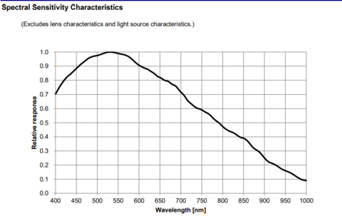
4 Spectral Sensitivity Characteristics
| Sensor | Spectral Sensitivity |
| IMX178LLJ-C |
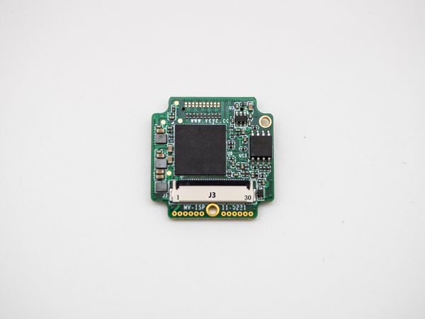
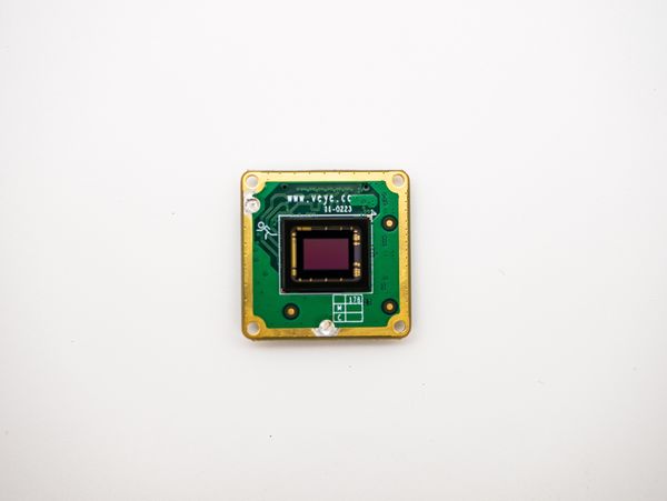
5 Interface & Pin list
| J3: CSI-2 Interface,Up Contact | ||
| Pin NO. | NAME | Remarks |
| 1 | GND | |
| 2 | VCC | 5V |
| 3 | VCC | 5V |
| 4 | VCC | 5V |
| 5 | VCC | 5V |
| 6 | GND | |
| 7 | ENABLE | Power Enable,3.3V,ACTIVE High |
| 8 | GND | |
| 9 | MIPI_L0_N | Lane 0 Negative |
| 10 | MIPI_L0_P | Lane 0 Positive |
| 11 | GND | |
| 12 | MIPI_L1_N | Lane 1 Negative |
| 13 | MIPI_L1_P | Lane 1 Positive |
| 14 | GND | |
| 15 | MIPI_CK_N | CLK Negative |
| 16 | MIPI_CK_P | CLK Positive |
| 17 | GND | |
| 18 | MIPI_L2_N | Reserved |
| 19 | MIPI_L2_P | Reserved |
| 20 | GND | |
| 21 | MIPI_L3_N | Reserved |
| 22 | MIPI_L3_P | Reserved |
| 23 | GND | |
| 24 | SCL | I2C SCL, 3.3V Level |
| 25 | SDA | I2C SDA, 3.3V Level |
| 26 | GPIO3 | Reserved |
| 27 | OUT_IO2 | Multi-function Port 2,3.3V level |
| 28 | OUT_IO1 | Multi-function Port 1,3.3V level |
| 29 | TriggerIN_IO | Hardware Trigger in,3.3V level |
| 30 | GND | |
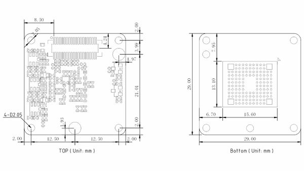
6 Board Dimension
7 PCBA 3D STP File

