FPD LINK III for Jetson
1 Introduction
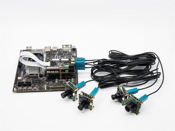
FPD-Link SerDes III is a coaxial remote transmission scheme of video stream provided by TI. We have designed FPD-LINK3-TX and FPD-LINK3-2RX boards, which can realize coaxial transmission of 1 or 2 channels of MIPI CSI-2 images, and the transmission distance can be up to 8meters(RG174 RF Cable) or 10meters(RG58 RF Cable).
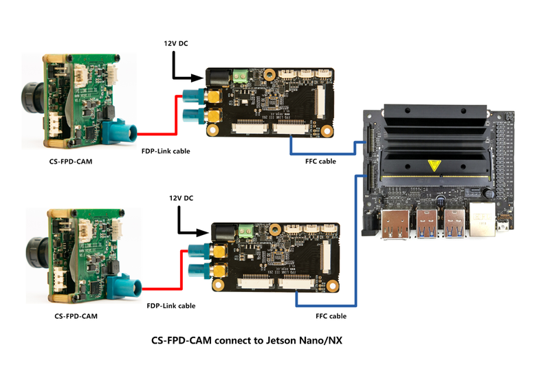
On Jetson Nano/NX platform, a set of FPD-LINK3-TX and FPD-LINK3-2RX boards are used to realize the remote transmission of 1-channel video. The I2C address of the camera after initialization configuration is the same as that of the original camera.On FPD-LINK3-2RX board, fpdlink channel is from port0(J3) to J9.
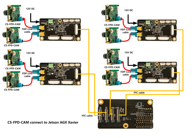
On Jetson TX2/AGX Xavier platform, a set of FPD-LINK3-TX and FPD-LINK3-2RX boards are used to realize the remote transmission of 2-channel video. On FPD-LINK3-2RX board, fpdlink channel is from port0(J3) and port1(J4) to J7. J7 is a MIPI interface of 4 lan, which supports two independent camera data transmission through virtual channel technology.
For application layer, it support all MIPI camera functions, including image, i2C communication, synchronous IO and trigger IO.
Therefore, when using CS-FPD-CAM, you must refer to the following article:
2 Hardware Setup
PS:
- FPD-LINK3-2RX need a 12V DC power.
- FPD-LINK3-2RX needs power up no later than Xavier . Because Xavier detects peripherals during the startup phase.
- Be sure to screw the ADP adapter board to the bottom board.
3 Upgrade Jetson Nano, Jetson TX2, AGX Xavier and Xavier NX system
The steps are basically the same as Upgrade Jetson Nano, Jetson TX2, AGX Xavier and Xavier NX. Note that dts, dtb, use the version with the fpdlink suffix. Driver source code and Image, are compatible with FPD-Link and MIPI interface cameras.
3.1 Are Image and DTB upgrade successful ?
3.1.1 For Image
ls /sys/bus/i2c/drivers/
There should have veyecam2m veye327 csx307 cssc132 i2c-ds90ub954 directory.
3.1.2 For DTB
DTB varies from platform and from camera module.
- Nano A02
ls /proc/device-tree/host1x/i2c@546c0000/
- Nano B01
ls /proc/device-tree/cam_i2cmux/i2c@*
- TX2 Devkit
ls /proc/device-tree/i2c@3180000/tca9548@70/i2c@*
- AGX Xavier
ls /proc/device-tree/i2c@3180000/tca9548@70/i2c@*
- Xavier NX and TX2 NX(p3509-0000 carrier board)
ls /proc/device-tree/cam_i2cmux/i2c@*
You should be able to find the camera model you used and ds90ub954.
4 I2C Address
fpdlink port:FPD-LINK3-2RX,J3 is port 0, J4 is port 1.
4.1 Nano A02
| Camera Index | I2C bus | I2C Addr | Location |
|---|---|---|---|
| Camera 0 | 6 | 0x3b | FPD-LINK3-2RX port 0 |
4.2 Nano B01
| Camera Index | I2C bus | I2C Addr | Location |
|---|---|---|---|
| Camera 0 | 7 | 0x3b | FPD-LINK3-2RX port 0 |
| Camera 1 | 8 | 0x3b | FPD-LINK3-2RX port 0 |
4.3 Xavier NX and TX2 NX(p3509-0000 carrier board)
| Camera Index | I2C bus | I2C Addr | Location |
|---|---|---|---|
| Camera 0 | 9 | 0x3b | FPD-LINK3-2RX port 0 |
| Camera 1 | 10 | 0x3b | FPD-LINK3-2RX port 0 |
4.4 AGX Xavier
| Camera Index | I2C bus | I2C Addr | Location |
|---|---|---|---|
| Camera 0 | 30 | 0x3b | ADP-N3 J1--FPD-LINK3-2RX port 0 |
| Camera 1 | 30 | 0x3c | ADP-N3 J1--FPD-LINK3-2RX port 1 |
| Camera 2 | 31 | 0x3b | ADP-N3 J2--FPD-LINK3-2RX port 0 |
| Camera 3 | 31 | 0x3c | ADP-N3 J2--FPD-LINK3-2RX port 1 |
| Camera 4 | 32 | 0x3b | ADP-N3 J3--FPD-LINK3-2RX port 0 |
| Camera 5 | 32 | 0x3c | ADP-N3 J3--FPD-LINK3-2RX port 1 |
| Camera 6 | 33 | 0x3b | ADP-N3 J4--FPD-LINK3-2RX port 0 |
| Camera 7 | 33 | 0x3c | ADP-N3 J4--FPD-LINK3-2RX port 1 |
4.5 TX2 Devkit
| Camera Index | I2C bus | I2C Addr | Location |
|---|---|---|---|
| Camera 0 | 30 | 0x3b | ADP-N2 J1--FPD-LINK3-2RX port 0 |
| Camera 1 | 30 | 0x3c | ADP-N2 J1--FPD-LINK3-2RX port 1 |
| Camera 2 | 31 | 0x3b | ADP-N2 J2--FPD-LINK3-2RX port 0 |
| Camera 3 | 31 | 0x3c | ADP-N2 J2--FPD-LINK3-2RX port 1 |
| Camera 4 | 32 | 0x3b | ADP-N2 J3--FPD-LINK3-2RX port 0 |
| Camera 5 | 32 | 0x3c | ADP-N2 J3--FPD-LINK3-2RX port 1 |
4.6 Applications and Test
The same as Applications and Test on Jetson of MIPI Camera.
5 FPD-Link III shell script manual
$ ./fpdlink3_i2c_jetson.sh
Usage: ./fpdlink3_i2c_jetson.sh [-f] function name -b bus -p port -p1 param1 -p2 param2 -p3 param3
options:
-f [function name] function name
-b [i2c bus num] i2c bus number
-p [fpdlink port] fpd link port number [0,1]
-p1 [param1] param1 of each function
-p2 [param1] param2 of each function
-p3 [param1] param3 of each function
support functions: rpi_init,sync_init,trigger_init
fpdlink port:FPD-LINK3-2RX,J3 is port 0, J4 is port 1.
5.1 fpdlink3_i2c.sh Usage
The probing and loading of FPD-Link devices are completed automatically when the system is powered on.
5.1.1 sync_init
./fpdlink3_i2c_jetson.sh -f sync_init -b [busnum] -p [portnum] -p1 0
Configure the camera on I2C bus [busnum], port [portnum] as the master of sync mode.
Connect J1 of FPD-LINK3-TX on port [portnum] to J6 of FPD-LINK3-2RX,direction is TX-->RX.
./fpdlink3_i2c_jetson.sh -f sync_init -b [busnum] -p [portnum] -p1 1
Configure the camera on I2C bus [busnum], port [portnum] as the slave of sync mode.
Connect J8 of FPD-LINK3-2RX on port [portnum] to J1 of FPD-LINK3-TX ,direction is RX-->TX.
5.1.2 trigger_init
./fpdlink3_i2c_jetson.sh -f trigger_init -b [busnum] -p [portnum]
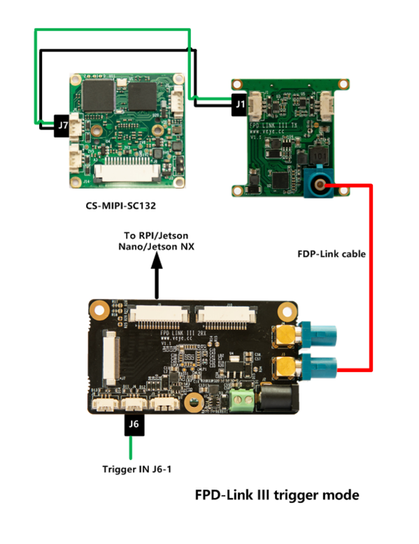
Configure the camera on I2C bus [busnum], port [portnum] as the trigger mode.
Connect J6-0 of FPD-LINK3-2RX on port [portnum] to J1-0 of FPD-LINK3-TX ,direction is RX-->TX.
6 Typical application
6.1 CS-FPD-CAM Video usage, connnect to Jetson Nano B01/NX
6.2 CS-FPD-CAM Video usage, connnect to Jetson AGX Xavier
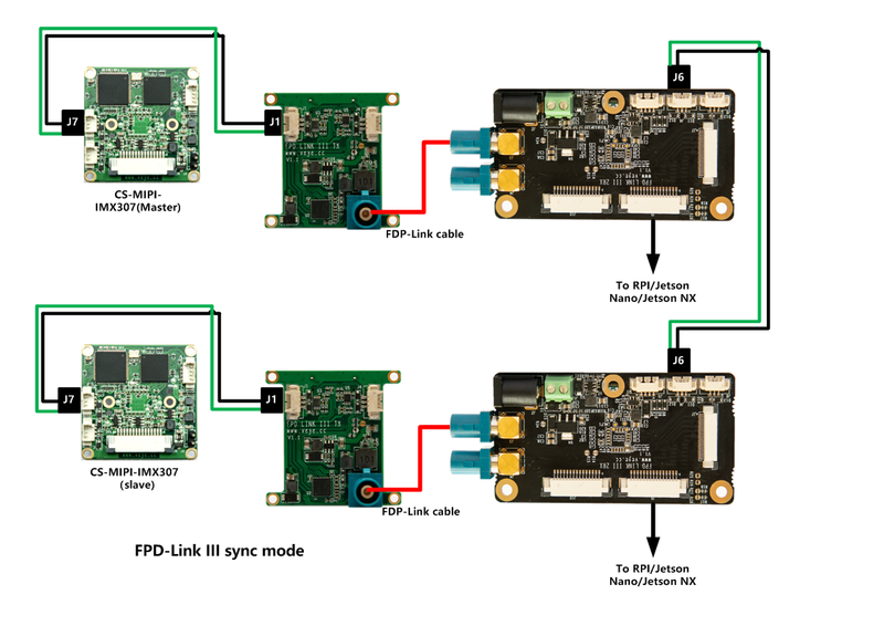
6.3 CS-FPD-CAM-IMX307 sync mode,connnect to Jetson Nano B01/NX
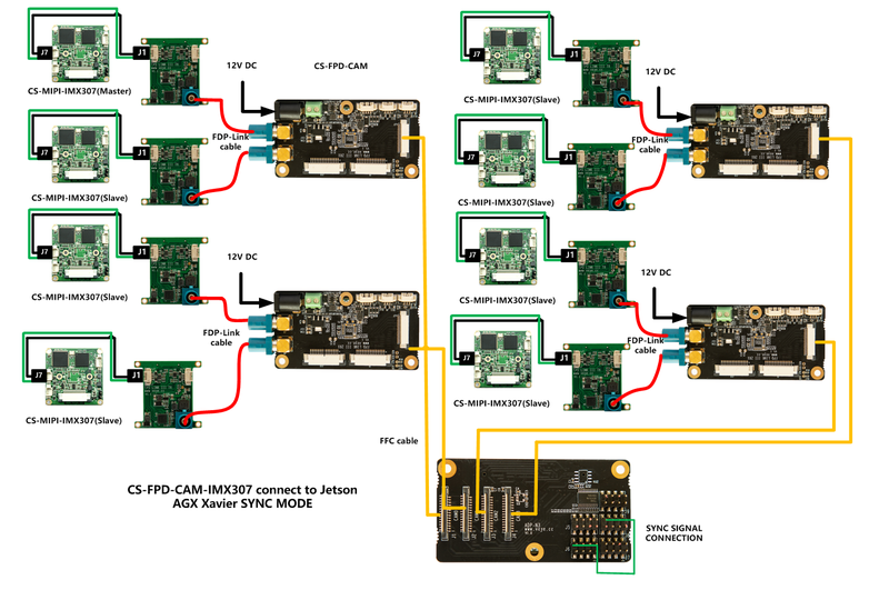
SYNC signal connect J7-3 to J1-3,J7-2 to J1-2.
6.3.1 Step 1:
On the motherboard of the two cameras, execute:
ls /dev/video*
The presence of a video0,video1, indicates that the camera has been correctly detected and the video can be connected.
6.3.2 Step 2:
After Step 1,
- Configure cam0 as the master
./fpdlink3_i2c.sh -f sync_init -p 0 -p1 0 -b [i2c_bus_num]
./cs_mipi_i2c.sh -w -f streammode -p1 1 -p2 0 -b [i2c_bus_num] -d 0x3b
- Configure cam1 as the slave
./fpdlink3_i2c.sh -f sync_init -p 0 -p1 1 -b [i2c_bus_num]
./cs_mipi_i2c.sh -w -f streammode -p1 1 -p2 1 -b [i2c_bus_num] -d 0x3b
6.3.3 Step 3:
The stream acquisition and I2C instruction control of the camera are exactly the same as those of the camera with the MIPI interface now.
6.4 CS-FPD-CAM-IMX307 sync mode,connnect to Jetson AGX Xavier
SYNC signal connect J7-3 to J1-3,J7-2 to J1-2.
6.4.1 Step 1:
On the motherboard of the two cameras, execute:
ls /dev/video*
The presence of a video0-7, indicates that the camera has been correctly detected and the video can be connected.
6.4.2 Step 2:
After Step 1,
- Configure cam0 as the master
./fpdlink3_i2c.sh -f sync_init -p 0 -p1 0 -b [i2c_bus_num]
./cs_mipi_i2c.sh -w -f streammode -p1 1 -p2 0 -b [i2c_bus_num] -d 0x3b
- Configure cam1-cam7 as the slave
./fpdlink3_i2c_jetson.sh -f sync_init -p 1 -p1 1 -b 30
./cs_mipi_i2c.sh -w -f streammode -p1 1 -p2 1 -b 30 -d 0x3c
./fpdlink3_i2c_jetson.sh -f sync_init -p 0 -p1 1 -b 31
./cs_mipi_i2c.sh -w -f streammode -p1 1 -p2 1 -b 31 -d 0x3b
./fpdlink3_i2c_jetson.sh -f sync_init -p 1 -p1 1 -b 31
./cs_mipi_i2c.sh -w -f streammode -p1 1 -p2 1 -b 31 -d 0x3c
./fpdlink3_i2c_jetson.sh -f sync_init -p 0 -p1 1 -b 32
./cs_mipi_i2c.sh -w -f streammode -p1 1 -p2 1 -b 32 -d 0x3b
./fpdlink3_i2c_jetson.sh -f sync_init -p 1 -p1 1 -b 32
./cs_mipi_i2c.sh -w -f streammode -p1 1 -p2 1 -b 32 -d 0x3c
./fpdlink3_i2c_jetson.sh -f sync_init -p 0 -p1 1 -b 33
./cs_mipi_i2c.sh -w -f streammode -p1 1 -p2 1 -b 33 -d 0x3b
./fpdlink3_i2c_jetson.sh -f sync_init -p 1 -p1 1 -b 33
./cs_mipi_i2c.sh -w -f streammode -p1 1 -p2 1 -b 33 -d 0x3c
6.4.3 Step 3:
The stream acquisition and I2C instruction control of the camera are exactly the same as those of the camera with the MIPI interface now.
6.4.4 SYNC signal connection:
The synchronization signal is connected as shown in the figure above. J6 is connected with J8's 2, 4, 6 and 8pin.
For the schematic diagram of the SYNC signal, please refer to:
6.5 CS-FPD-CAM-SC132 Trigger mode,connnect to Jetson Nano B01/NX
SYNC signal connect J7-1 to J1-1,J7-2 to J1-2.
6.5.1 Step 1:
On the motherboard of the camera, execute:
ls /dev/video*
The presence of a video0, indicates that the camera has been correctly detected and the video can be connected.
6.5.2 Step 2:
./fpdlink3_i2c_jetson.sh -f trigger_init -p 0 -b [i2c_bus_num] -d 0x3b
./cs_mipi_i2c.sh -w -f streammode -p1 3 -b [i2c_bus_num] -d 0x3b
Configure port 0 as trigger mode.
6.5.3 Step 3:
After Step 1, the I2C to control camera is ready.The stream acquisition and I2C instruction control of the camera are exactly the same as those of the camera with the MIPI interface now.
Refer to Camera_module_Trigger_Mode_manual to configure the camera.
6.6 CS-FPD-CAM-SC132 Trigger mode,connnect to Jetson AGX Xavier
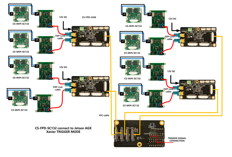
SYNC signal connect J7-1 to J1-1,J7-2 to J1-2.
6.6.1 Step 1:
On the motherboard of the camera, execute:
ls /dev/video*
The presence of a video0-7, indicates that the camera has been correctly detected and the video can be connected.
6.6.2 Step 2:
./fpdlink3_i2c_jetson.sh -f trigger_init -p 0 -b 30 -d 0x3b
./cs_mipi_i2c.sh -w -f streammode -p1 3 -b 30 -d 0x3b
./fpdlink3_i2c_jetson.sh -f trigger_init -p 1 -b 30 -d 0x3c
./cs_mipi_i2c.sh -w -f streammode -p1 3 -b 30 -d 0x3c
./fpdlink3_i2c_jetson.sh -f trigger_init -p 0 -b 31 -d 0x3b
./cs_mipi_i2c.sh -w -f streammode -p1 3 -b 31 -d 0x3b
./fpdlink3_i2c_jetson.sh -f trigger_init -p 1 -b 31 -d 0x3c
./cs_mipi_i2c.sh -w -f streammode -p1 3 -b 31 -d 0x3c
./fpdlink3_i2c_jetson.sh -f trigger_init -p 0 -b 32 -d 0x3b
./cs_mipi_i2c.sh -w -f streammode -p1 3 -b 32 -d 0x3b
./fpdlink3_i2c_jetson.sh -f trigger_init -p 1 -b 32 -d 0x3c
./cs_mipi_i2c.sh -w -f streammode -p1 3 -b 32 -d 0x3c
./fpdlink3_i2c_jetson.sh -f trigger_init -p 0 -b 33 -d 0x3b
./cs_mipi_i2c.sh -w -f streammode -p1 3 -b 33 -d 0x3b
./fpdlink3_i2c_jetson.sh -f trigger_init -p 1 -b 33 -d 0x3c
./cs_mipi_i2c.sh -w -f streammode -p1 3 -b 33 -d 0x3c
./fpdlink3_i2c_jetson.sh -f trigger_init -p 0 -b 34 -d 0x3b
./cs_mipi_i2c.sh -w -f streammode -p1 3 -b 34 -d 0x3b
./fpdlink3_i2c_jetson.sh -f trigger_init -p 1 -b 34 -d 0x3c
./cs_mipi_i2c.sh -w -f streammode -p1 3 -b 34 -d 0x3c
Configure all cameras as trigger mode.
6.6.3 Step 3:
After Step 1, the I2C to control camera is ready.The stream acquisition and I2C instruction control of the camera are exactly the same as those of the camera with the MIPI interface now.
Refer to Camera_module_Trigger_Mode_manual to configure the camera.

