Difference between revisions of "Mv series camera appnotes 4 jetson"
| (19 intermediate revisions by the same user not shown) | |||
| Line 39: | Line 39: | ||
|RAW series | |RAW series | ||
|RAW-MIPI-SC132M | |RAW-MIPI-SC132M | ||
| + | |Done | ||
| + | |- | ||
| + | |RAW series | ||
| + | |RAW-MIPI-IMX462M | ||
| + | |Done | ||
| + | |- | ||
| + | |RAW series | ||
| + | |RAW-MIPI-AR0234M | ||
|Done | |Done | ||
|} | |} | ||
| + | In addition, the driver for the V-by-One HS connection mode has been finished. | ||
==== Jetson Board List ==== | ==== Jetson Board List ==== | ||
| Line 85: | Line 94: | ||
*Jetpack5.1,L4T r35.2.1 | *Jetpack5.1,L4T r35.2.1 | ||
*Jetpack5.1.1,L4T r35.3.1 | *Jetpack5.1.1,L4T r35.3.1 | ||
| + | *Jetpack5.1.2,L4T r35.4.1 | ||
=====How to check the current L4T version===== | =====How to check the current L4T version===== | ||
| Line 100: | Line 110: | ||
MV series cameras require an adapter board to access the Jetson platform. The following table shows the support status. | MV series cameras require an adapter board to access the Jetson platform. The following table shows the support status. | ||
{| class="wikitable" | {| class="wikitable" | ||
| + | !Camera Model | ||
!Jetson Board | !Jetson Board | ||
!adapter board | !adapter board | ||
| − | ! camera number | + | !FFC(to adapter board) |
| − | ! | + | !FFC(to Jetson board) |
| + | !camera number | ||
| + | !extra power | ||
|- | |- | ||
| + | | rowspan="10" |MV Series | ||
|Nano A02 | |Nano A02 | ||
|ADP-MV1 | |ADP-MV1 | ||
| + | |30pin Opposite-side contacts FFC | ||
| + | |15pin Opposite-side contacts FFC | ||
|1 | |1 | ||
|5V DC(Required) | |5V DC(Required) | ||
|- | |- | ||
|Nano B01 | |Nano B01 | ||
| − | | ADP-MV1 | + | |ADP-MV1 |
| − | | | + | |30pin Opposite-side contacts FFC |
| + | |15pin Opposite-side contacts FFC | ||
| + | |2 | ||
|5V DC(Required) | |5V DC(Required) | ||
|- | |- | ||
|Nano 2GB | |Nano 2GB | ||
|ADP-MV1 | |ADP-MV1 | ||
| − | | | + | |30pin Opposite-side contacts FFC |
| − | | 5V DC(Required) | + | |15pin Opposite-side contacts FFC |
| + | |1 | ||
| + | |5V DC(Required) | ||
|- | |- | ||
|TX2 NX | |TX2 NX | ||
|ADP-MV1 | |ADP-MV1 | ||
| + | |30pin Opposite-side contacts FFC | ||
| + | |15pin Opposite-side contacts FFC | ||
|2 | |2 | ||
|5V DC(Required) | |5V DC(Required) | ||
| Line 127: | Line 149: | ||
|XAVIER NX | |XAVIER NX | ||
|ADP-MV1 | |ADP-MV1 | ||
| + | |30pin Opposite-side contacts FFC | ||
| + | |15pin Opposite-side contacts FFC | ||
|2 | |2 | ||
|5V DC(Required) | |5V DC(Required) | ||
|- | |- | ||
|Orin Nano | |Orin Nano | ||
| − | |ADP-MV1 | + | |ADP-MV1 |
| + | |30pin Opposite-side contacts FFC | ||
| + | |15-to-22 pin Same-side contacts FFC | ||
|2 | |2 | ||
|5V DC(Required) | |5V DC(Required) | ||
|- | |- | ||
|Orin NX | |Orin NX | ||
| − | |ADP-MV1 | + | |ADP-MV1 |
| + | |30pin Opposite-side contacts FFC | ||
| + | |15-to-22 pin Same-side contacts FFC | ||
|2 | |2 | ||
|5V DC(Required) | |5V DC(Required) | ||
|- | |- | ||
| − | | TX2 Devkit | + | |TX2 Devkit |
| + | |ADP-N4 | ||
| + | |30pin Opposite-side contacts FFC | ||
| + | |board-to-board connector | ||
| + | |6 | ||
| + | |5V or 12V DC (Required) | ||
| + | |- | ||
| + | |AGX Xavier | ||
|ADP-N4 | |ADP-N4 | ||
| + | |30pin Opposite-side contacts FFC | ||
| + | |board-to-board connector | ||
|6 | |6 | ||
| 5V or 12V DC (Required) | | 5V or 12V DC (Required) | ||
|- | |- | ||
| − | |AGX | + | |AGX Orin |
|ADP-N4 | |ADP-N4 | ||
| + | |30pin Opposite-side contacts FFC | ||
| + | |board-to-board connector | ||
|6 | |6 | ||
|5V or 12V DC (Required) | |5V or 12V DC (Required) | ||
|- | |- | ||
| − | |Orin | + | | rowspan="10" |RAW-MIPI-SC132M |
| − | | ADP- | + | |Nano A02 |
| + | |N/A | ||
| + | |N/A | ||
| + | |15pin Opposite-side contacts FFC | ||
| + | |1 | ||
| + | |N/A | ||
| + | |- | ||
| + | |Nano B01 | ||
| + | |N/A | ||
| + | |N/A | ||
| + | |15pin Opposite-side contacts FFC | ||
| + | |2 | ||
| + | |N/A | ||
| + | |- | ||
| + | |Nano 2GB | ||
| + | |N/A | ||
| + | |N/A | ||
| + | |15pin Opposite-side contacts FFC | ||
| + | |1 | ||
| + | |N/A | ||
| + | |- | ||
| + | |TX2 NX | ||
| + | |N/A | ||
| + | |N/A | ||
| + | |15pin Opposite-side contacts FFC | ||
| + | |2 | ||
| + | |N/A | ||
| + | |- | ||
| + | |XAVIER NX | ||
| + | |N/A | ||
| + | |N/A | ||
| + | |15pin Opposite-side contacts FFC | ||
| + | |2 | ||
| + | |N/A | ||
| + | |- | ||
| + | |Orin Nano | ||
| + | |N/A | ||
| + | |N/A | ||
| + | |15-to-22 pin Same-side contacts FFC | ||
| + | |2 | ||
| + | |N/A | ||
| + | |- | ||
| + | |Orin NX | ||
| + | |N/A | ||
| + | |N/A | ||
| + | |15-to-22 pin Same-side contacts FFC | ||
| + | |2 | ||
| + | |N/A | ||
| + | |- | ||
| + | |TX2 Devkit | ||
| + | |ADP-N5 | ||
| + | |15pin Opposite-side contacts FFC | ||
| + | |board-to-board connector | ||
| + | |6 | ||
| + | |N/A | ||
| + | |- | ||
| + | |AGX Xavier | ||
| + | |ADP-N5 | ||
| + | |15pin Opposite-side contacts FFC | ||
| + | |board-to-board connector | ||
| + | |6 | ||
| + | |N/A | ||
| + | |- | ||
| + | |AGX Orin | ||
| + | |ADP-N5 | ||
| + | |15pin Opposite-side contacts FFC | ||
| + | |board-to-board connector | ||
| + | |6 | ||
| + | |N/A | ||
| + | |- | ||
| + | | rowspan="10" |RAW Series(Except for RAW-MIPI-SC132M) | ||
| + | |Nano A02 | ||
| + | |N/A | ||
| + | |N/A | ||
| + | |15-to-22 pin Same-side contacts FFC | ||
| + | |1 | ||
| + | |N/A | ||
| + | |- | ||
| + | |Nano B01 | ||
| + | |N/A | ||
| + | |N/A | ||
| + | |15-to-22 pin Same-side contacts FFC | ||
| + | |2 | ||
| + | |N/A | ||
| + | |- | ||
| + | |Nano 2GB | ||
| + | |N/A | ||
| + | |N/A | ||
| + | |15-to-22 pin Same-side contacts FFC | ||
| + | |1 | ||
| + | |N/A | ||
| + | |- | ||
| + | |TX2 NX | ||
| + | |N/A | ||
| + | |N/A | ||
| + | |15-to-22 pin Same-side contacts FFC | ||
| + | |2 | ||
| + | |N/A | ||
| + | |- | ||
| + | |XAVIER NX | ||
| + | |N/A | ||
| + | |N/A | ||
| + | |15-to-22 pin Same-side contacts FFC | ||
| + | |2 | ||
| + | |N/A | ||
| + | |- | ||
| + | |Orin Nano | ||
| + | |N/A | ||
| + | |N/A | ||
| + | |22pin Opposite-side contacts FFC | ||
| + | |2 | ||
| + | |N/A | ||
| + | |- | ||
| + | |Orin NX | ||
| + | |N/A | ||
| + | |N/A | ||
| + | |22pin Opposite-side contacts FFC | ||
| + | |2 | ||
| + | |N/A | ||
| + | |- | ||
| + | |TX2 Devkit | ||
| + | |ADP-N5 | ||
| + | |15-to-22 pin Same-side contacts FFC | ||
| + | |board-to-board connector | ||
| + | |6 | ||
| + | |N/A | ||
| + | |- | ||
| + | |AGX Xavier | ||
| + | |ADP-N5 | ||
| + | |15-to-22 pin Same-side contacts FFC | ||
| + | |board-to-board connector | ||
|6 | |6 | ||
| − | | | + | |N/A |
| + | |- | ||
| + | |AGX Orin | ||
| + | |ADP-N5 | ||
| + | |15-to-22 pin Same-side contacts FFC | ||
| + | |board-to-board connector | ||
| + | |6 | ||
| + | |N/A | ||
|} | |} | ||
| − | ==== Connection of MV | + | ==== MV series cameras use the ADP-MV1 connection ==== |
| − | The two are connected using 0.5 mm pitch*30P FFC cable with | + | |
| + | ===== Connection of MV series cameras and ADP-MV1 ===== | ||
| + | The two are connected using 0.5 mm pitch*30P FFC cable with Opposite-side contacts. The cable must be inserted with the silver contacts facing outside. | ||
{| class="wikitable" | {| class="wikitable" | ||
!TOP | !TOP | ||
| Line 165: | Line 343: | ||
|[[File:ADP-MV1-MV-MIPI-X 02.jpg|alt=|center|thumb|600x600px|ADP-MV1 to MV-MIPI-X]] | |[[File:ADP-MV1-MV-MIPI-X 02.jpg|alt=|center|thumb|600x600px|ADP-MV1 to MV-MIPI-X]] | ||
|} | |} | ||
| − | |||
| − | |||
===== Power supply ===== | ===== Power supply ===== | ||
The ADP-MV1 requires a separate 5V power supply and can be powered directly from the Jetson board using a Dupont cable. | The ADP-MV1 requires a separate 5V power supply and can be powered directly from the Jetson board using a Dupont cable. | ||
[[File:ADP-MV1-MV-MIPI-X 07.jpg|alt=ADP-MV1 power supply|center|thumb|800x800px|ADP-MV1 power supply]] | [[File:ADP-MV1-MV-MIPI-X 07.jpg|alt=ADP-MV1 power supply|center|thumb|800x800px|ADP-MV1 power supply]] | ||
| − | |||
| − | ==== Connection with Nano and NX using ADP-MV1 ==== | + | ===== Connection with Nano and NX using ADP-MV1 ===== |
The Nano Series and NX Series are connected in this way. | The Nano Series and NX Series are connected in this way. | ||
[[File:MV camera and Xavier NX connection.jpg|alt=MV camera and Xavier NX connection|center|thumb|800x800px|MV camera and Xavier NX connection]] | [[File:MV camera and Xavier NX connection.jpg|alt=MV camera and Xavier NX connection|center|thumb|800x800px|MV camera and Xavier NX connection]] | ||
| − | |||
| − | ==== Connection of MV- | + | ===== Connection with Orin Nano and NX using ADP-MV1 ===== |
| − | The two are connected using 0.5 mm pitch*30P FFC cable with | + | Use a 15P to 22 pin FFC Cable with the Same-side contacts. Pay attention to the direction of the contact surface. |
| + | [[File:MV camera connect to Orin Nano and Orin NX.jpg|center|thumb|800x800px|MV camera connect to Orin Nano and Orin NX]] | ||
| + | |||
| + | ==== MV series cameras use the ADP-N4 connection ==== | ||
| + | |||
| + | ===== Connection of MV series cameras and ADP-N4 ===== | ||
| + | The two are connected using 0.5 mm pitch*30P FFC cable with Same-side contacts. The cable must be inserted with the silver contacts facing outside. | ||
[[File:ADP-N4 and MV-MIPI-CAM.jpg|link=http://wiki.veye.cc/index.php/File:ADP-N4%20and%20MV-MIPI-CAM.jpg|center|thumb|800x800px|MV-MIPI-CAM to ADP-N4]] | [[File:ADP-N4 and MV-MIPI-CAM.jpg|link=http://wiki.veye.cc/index.php/File:ADP-N4%20and%20MV-MIPI-CAM.jpg|center|thumb|800x800px|MV-MIPI-CAM to ADP-N4]] | ||
<br /> | <br /> | ||
| − | |||
===== Power supply ===== | ===== Power supply ===== | ||
The ADP-N4 requires power supply. It supports two types of power supply, any one of them will work. | The ADP-N4 requires power supply. It supports two types of power supply, any one of them will work. | ||
| Line 190: | Line 369: | ||
* 12V DC is connected to J11, which needs to be powered by an external adapter. | * 12V DC is connected to J11, which needs to be powered by an external adapter. | ||
| − | ===== Connection with TX2 | + | ===== Connection with TX2 Devkit and AGX Series using ADP-N4 ===== |
[[File:ADP-N4 to AGX XAVIER.jpg|alt=ADP-N4 to AGX XAVIER|center|thumb|800x800px|ADP-N4 to AGX XAVIER]] | [[File:ADP-N4 to AGX XAVIER.jpg|alt=ADP-N4 to AGX XAVIER|center|thumb|800x800px|ADP-N4 to AGX XAVIER]] | ||
[[File:ADP-N4 to AGX Orin.jpg|center|thumb|800x800px|ADP-N4 to AGX Orin]] | [[File:ADP-N4 to AGX Orin.jpg|center|thumb|800x800px|ADP-N4 to AGX Orin]] | ||
[[File:ADP-N4 to TX2 Devkit.jpg|center|thumb|800x800px|ADP-N4 to TX2 Devkit]] | [[File:ADP-N4 to TX2 Devkit.jpg|center|thumb|800x800px|ADP-N4 to TX2 Devkit]] | ||
| + | ==== RAW series cameras directly connected to the Jetson Board ==== | ||
| + | |||
| + | =====Connect to Nano or Xavier NX===== | ||
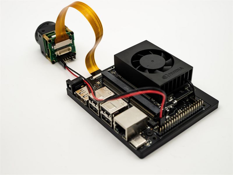
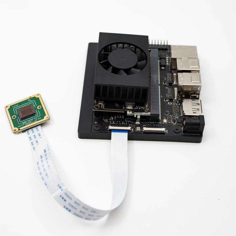
| + | The RAW-MIPI-SC132M use a 15-pin opposite-side FFC cable, while other RAW series cameras use a 15-to-22-pin same-side FFC cable.[[File:RAW-MIPI-AR0234-NANO 01.jpg|center|thumb|800x800px|RAW camera and Jetson Nano connection|link=http://wiki.veye.cc/index.php/File:RAW-MIPI-AR0234-NANO_01.jpg]] | ||
| + | =====Connet to Orin Nano or Orin NX ===== | ||
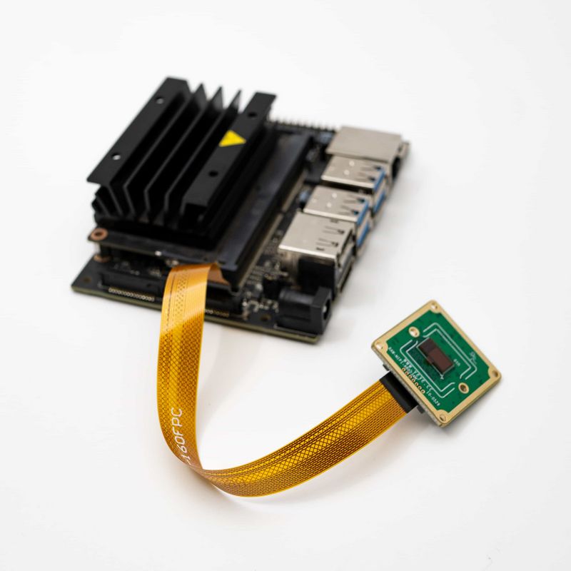
| + | The RAW-MIPI-SC132M use a 15-to-22-pin same-side FFC cable, while other RAW series cameras use a 22-pin opposite-side FFC cable.[[File:RAW-MIPI-IMX462-ORIN NX.jpg|center|thumb|800x800px|RAW-MIPI-IMX462-ORIN NX|link=http://wiki.veye.cc/index.php/File:RAW-MIPI-IMX462-ORIN_NX.jpg]] | ||
| + | |||
| + | ==== RAW series cameras use the ADP-N5 connection ==== | ||
| + | |||
| + | ===== Connection of RAW series cameras and ADP-N5 ===== | ||
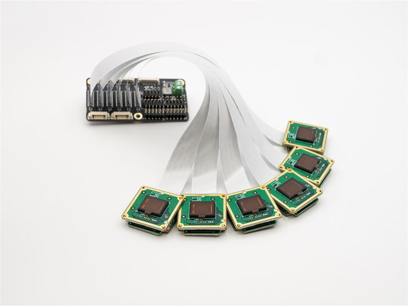
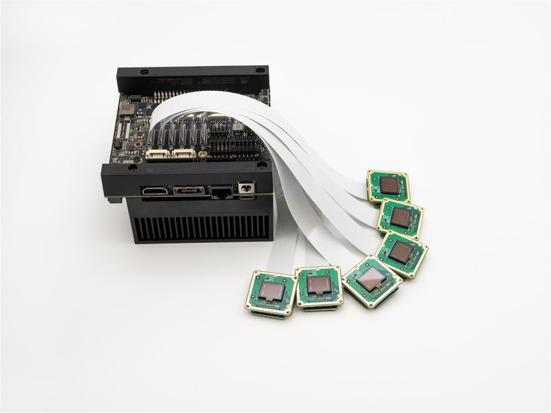
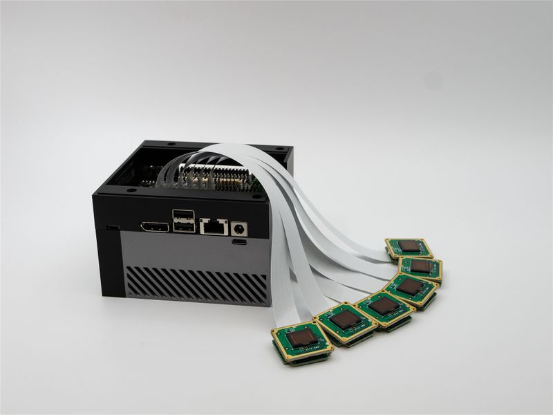
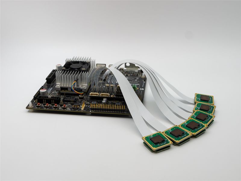
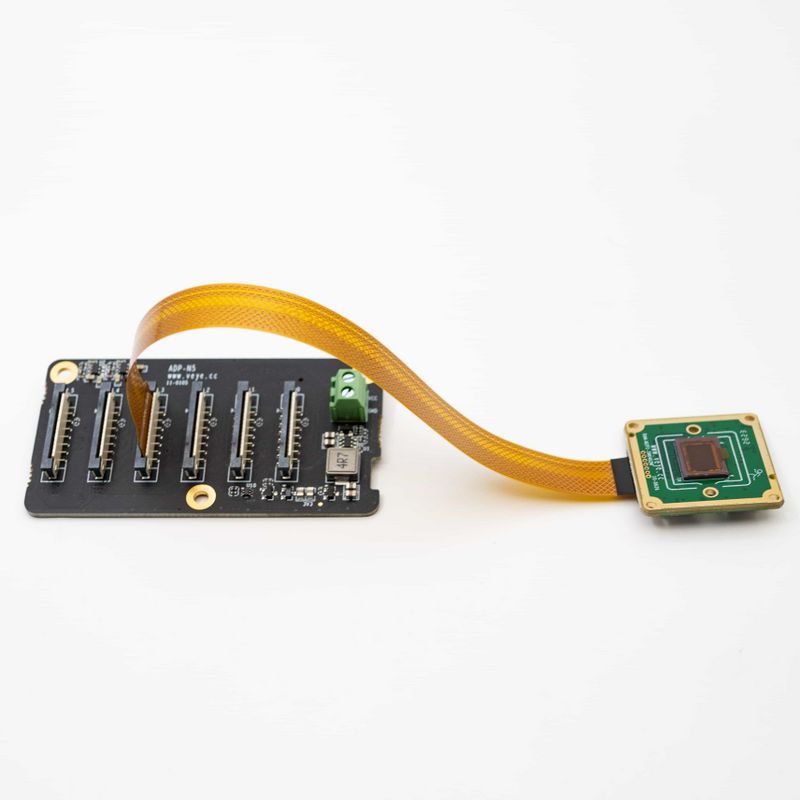
| + | The RAW-MIPI-SC132M use a 15-pin opposite-side FFC cable, while other RAW series cameras use a 15-to-22-pin same-side FFC cable.[[File:RAW-MIPI-IMX462-ADP-N5.jpg|center|thumb|800x800px|RAW-MIPI-IMX462 connect with ADP-N5|link=http://wiki.veye.cc/index.php/File:RAW-MIPI-IMX462-ADP-N5.jpg]]<br /> | ||
| + | =====Connection with TX2 Devkit and AGX Series using ADP-N5===== | ||
| + | [[File:RAW-MIPI-IMX462 connect to ADP-N5-AGX XAVIER.jpg|center|thumb|800x800px|ADP-N5 to AGX Xavier|link=http://wiki.veye.cc/index.php/File:RAW-MIPI-IMX462_connect_to_ADP-N5-AGX_XAVIER.jpg]]<br /> | ||
| + | ==== V-by-One-HS-KIT Camera Connection Diagram ==== | ||
| + | [[File:VBYONE connection with Jetson.jpg|center|thumb|800x800px|V-by-One-HS-KIT Camera Connection Diagram]] | ||
| + | <br /> | ||
=== Upgrade Jetson system === | === Upgrade Jetson system === | ||
This section describes how to upgrade the Jetson system to support MV camera module. For OS update method, please refer to [[VEYE CS Camera for Jetson TX2#Upgrade Jetson Nano.2C Jetson TX2.2C TX2 NX.2CAGX Xavier and Xavier NX system|Update Jetson OS]]. | This section describes how to upgrade the Jetson system to support MV camera module. For OS update method, please refer to [[VEYE CS Camera for Jetson TX2#Upgrade Jetson Nano.2C Jetson TX2.2C TX2 NX.2CAGX Xavier and Xavier NX system|Update Jetson OS]]. | ||
| Line 254: | Line 449: | ||
|V4L2_PIX_FMT_TX2_Y12 | |V4L2_PIX_FMT_TX2_Y12 | ||
|} | |} | ||
| − | =====XAVIER===== | + | =====XAVIER and Orin===== |
{| class="wikitable" | {| class="wikitable" | ||
!Depth | !Depth | ||
| Line 371: | Line 566: | ||
<code>export FPS=120</code> | <code>export FPS=120</code> | ||
| + | |||
| + | *RAW-MIPI-IMX462M | ||
| + | |||
| + | <code>export WIDTH=1920</code> | ||
| + | |||
| + | <code>export HEIGHT=1080</code> | ||
| + | |||
| + | <code>export FPS=60</code> | ||
| + | |||
| + | *RAW-MIPI-AR0234M | ||
| + | |||
| + | <code>export WIDTH=1920</code> | ||
| + | |||
| + | <code>export HEIGHT=1200</code> | ||
| + | |||
| + | <code>export FPS=60</code> | ||
=== v4l2-ctl Application examples === | === v4l2-ctl Application examples === | ||
| Line 641: | Line 852: | ||
<code>v4l2-ctl -d /dev/video0 --set-fmt-video=width=704,height=544,pixelformat=XY12 --stream-mmap --stream-count=1 --stream-to=y12-704x544.raw</code> | <code>v4l2-ctl -d /dev/video0 --set-fmt-video=width=704,height=544,pixelformat=XY12 --stream-mmap --stream-count=1 --stream-to=y12-704x544.raw</code> | ||
| + | ======RAW-MIPI-AR0234M====== | ||
| + | |||
| + | *raw8 | ||
| + | |||
| + | <code>v4l2-ctl -d /dev/video0 --set-fmt-video=width=1920,height=1200,pixelformat=GREY --stream-mmap --stream-count=1 --stream-to=y8-1920x1200.raw</code> | ||
| + | |||
| + | *raw10 | ||
| + | |||
| + | <code>v4l2-ctl -d /dev/video0 --set-fmt-video=width=1920,height=1200,pixelformat=XY10 --stream-mmap --stream-count=1 --stream-to=y10-1920x1200.raw</code> | ||
| + | ======RAW-MIPI-IMX462M====== | ||
| + | |||
| + | * raw10 | ||
| + | |||
| + | <code>v4l2-ctl -d /dev/video0 --set-fmt-video=width=1920,height=1088,pixelformat=XY10 --stream-mmap --stream-count=1 --stream-to=y10-1920x1088.raw</code> | ||
| + | |||
| + | *raw12 | ||
| + | |||
| + | <code>v4l2-ctl -d /dev/video0 --set-fmt-video=width=1920,height=1088,pixelformat=XY12 --stream-mmap --stream-count=1 --stream-to=y12-1920x1088.raw</code> | ||
For the image format, please refer to the section above: Description of raw data image format. | For the image format, please refer to the section above: Description of raw data image format. | ||
=====Preview===== | =====Preview===== | ||
| + | For cameras that support the GREY format, you can use qv4l2 or VLC for video preview. | ||
| + | |||
| + | ====== Preview using qv4l2 ====== | ||
| + | Install qv4l2, | ||
| + | |||
| + | <code>sudo apt install qv4l2</code> | ||
| + | |||
| + | 1. Open VLC with command line <code>vlc</code> to launch. | ||
| + | |||
| + | 2. Hit the <code>▶</code>(Play) button to call the open media window.[[File:Mvcam via qv4l2.png|center|thumb|800x800px|Play mv camera using qv4l2|link=http://wiki.veye.cc/index.php/File:Mvcam_via_qv4l2.png]]<br /> | ||
| + | ======Preview using VLC====== | ||
| + | Install vlc, | ||
| + | |||
| + | <code>sudo apt-get install vlc</code> | ||
| + | |||
| + | 1. Open VLC with command line <code>vlc</code> , or click the icon to launch. | ||
| + | |||
| + | 2. Hit the <code>▶</code>(Play) button to call the open media window. | ||
| + | |||
| + | 3. In <code>Capture Device</code> >> <code>Device Selection</code> >> <code>Video device name</code>, select the camera video node. | ||
| + | |||
| + | 4. Hit <code>Advanced Options...</code> button | ||
| + | |||
| + | 5. Type in the <code>width</code> and <code>height</code>, for example, 1280 and 1024. | ||
| + | 6. Hit <code>OK</code> to save the settings and see the video feed. | ||
| + | |||
| + | |||
| + | [[File:Mvcam via VLC.png|center|thumb|800x800px|Play mv camera using VLC|link=http://wiki.veye.cc/index.php/File:Mvcam_via_VLC.png]] | ||
====== Preview UYVY format images using gstreamer ====== | ====== Preview UYVY format images using gstreamer ====== | ||
| + | '''Note''': To increase the maximum frame rate and bandwidth, some modules no longer support the UYVY format. Please use the "fmtcap" command in the script to read the registers to confirm the specific configuration. | ||
| + | |||
The camera can be previewed in real time using the following command: | The camera can be previewed in real time using the following command: | ||
| Line 729: | Line 988: | ||
<code>v4l2-ctl -d /dev/video0 --set-fmt-video=width=704,height=544,pixelformat=GREY --stream-mmap --stream-count=-1 --stream-to=y8-704x544.raw</code> | <code>v4l2-ctl -d /dev/video0 --set-fmt-video=width=704,height=544,pixelformat=GREY --stream-mmap --stream-count=-1 --stream-to=y8-704x544.raw</code> | ||
| + | |||
| + | *RAW-MIPI-AR0234M | ||
| + | |||
| + | <code>v4l2-ctl -d /dev/video0 --set-fmt-video=width=1920,height=1200,pixelformat=GREY --stream-mmap --stream-count=-1 --stream-to=y8-1920x1200.raw</code> | ||
| + | |||
| + | *RAW-MIPI-IMX462M | ||
| + | |||
| + | <code>v4l2-ctl -d /dev/video0 --set-fmt-video=width=1920,height=1088,pixelformat=XY10 --stream-mmap --stream-count=-1 --stream-to=y8-1920x1088.raw</code> | ||
====== Perform soft trigger operation ====== | ====== Perform soft trigger operation ====== | ||
In other shell terminals, you can execute the following command multiple times for multiple triggers. | In other shell terminals, you can execute the following command multiple times for multiple triggers. | ||
| Line 914: | Line 1,181: | ||
<code>./yavta -c1 -Fy12-704x544.raw --skip 0 -f XY12 -s 704x544 /dev/video0</code> | <code>./yavta -c1 -Fy12-704x544.raw --skip 0 -f XY12 -s 704x544 /dev/video0</code> | ||
| + | ======RAW-MIPI-AR0234M====== | ||
| + | |||
| + | *raw8 | ||
| + | |||
| + | <code>./yavta -c1 -Fy8-1920x1200.raw --skip 0 -f Y8 -s 1920x1200 /dev/video0</code> | ||
| + | |||
| + | *raw10 | ||
| + | |||
| + | Take XAVIER as example. | ||
| + | |||
| + | <code>./yavta -c1 -Fy10-1920x1200.raw --skip 0 -f XY10 -s 1920x1200 /dev/video0</code> | ||
| + | ======RAW-MIPI-IMX462M====== | ||
| + | Take XAVIER as example. | ||
| + | |||
| + | *raw12 | ||
| + | |||
| + | <code>./yavta -c1 -Fy12-1920x1088.raw --skip 0 -f XY12 -s 1920x1088 /dev/video0</code> | ||
| + | |||
| + | *raw10 | ||
| + | |||
| + | <code>./yavta -c1 -Fy10-1920x1088.raw --skip 0 -f XY10 -s 1920x1088 /dev/video0</code> | ||
For the image format, please refer to the section above: Description of raw data image format. | For the image format, please refer to the section above: Description of raw data image format. | ||
| Line 922: | Line 1,210: | ||
===References=== | ===References=== | ||
===Document History=== | ===Document History=== | ||
| + | |||
| + | *2023-08-16 | ||
| + | |||
| + | Add support for RAW-MIPI-IMX462M and RAW-MIPI-AR0234M. | ||
| + | |||
| + | * 2023-07-31 | ||
| + | |||
| + | Support V-by-One. | ||
*2023-04-27 | *2023-04-27 | ||
Revision as of 16:33, 26 September 2023
1 Overview
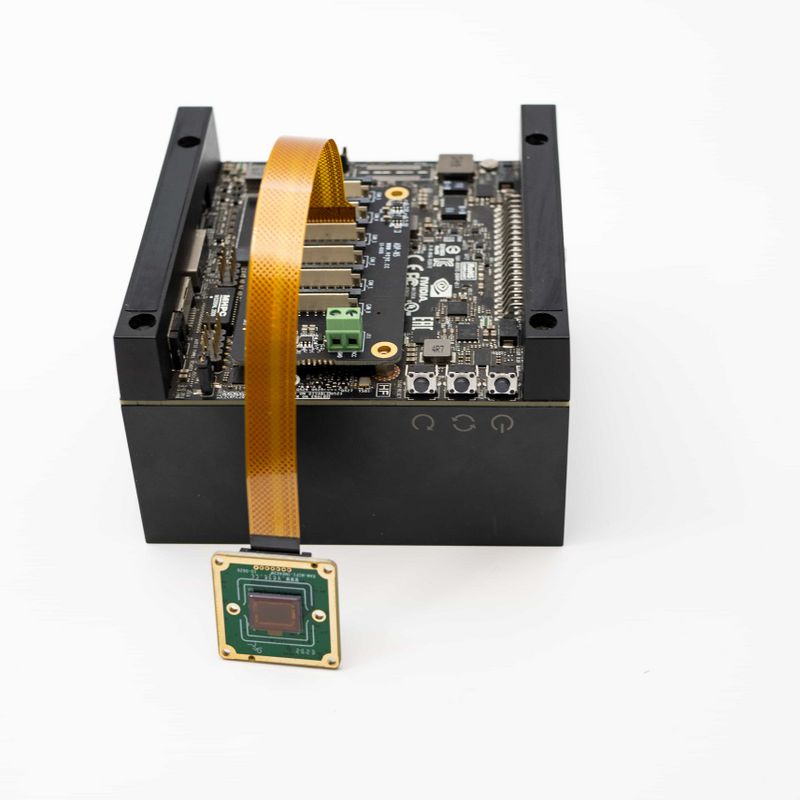
The MV series cameras are cameras introduced for AI applications in the industrial field. It uses the MIPI CSI-2 interface, which is especially suitable for embedded computing platforms.
It features rich data formats and trigger characteristics, extremely low latency, extremely high bandwidth and reliable stability.
This article describes how to use the MV series camera on the NVIDIA Jetson platform.
1.1 Camera Module List
| Series | Model | Status |
|---|---|---|
| MV series | MV-MIPI-IMX178M | Done |
| MV series | MV-MIPI-SC130M | Done |
| MV series | MV-MIPI-IMX296M | Done |
| MV series | MV-MIPI-IMX287M | Done |
| MV series | MV-MIPI-IMX265M | Done |
| MV series | MV-MIPI-IMX264M | Done |
| RAW series | RAW-MIPI-SC132M | Done |
| RAW series | RAW-MIPI-IMX462M | Done |
| RAW series | RAW-MIPI-AR0234M | Done |
In addition, the driver for the V-by-One HS connection mode has been finished.
1.2 Jetson Board List
| Jetson Board | Status |
|---|---|
| Nano A02 | Done |
| Nano B01 | Done |
| Nano 2GB | Done |
| TX2 NX | Done |
| XAVIER NX | Done |
| TX2 Devkit | Done |
| AGX Xavier | Done |
| AGX Orin | Done |
| Orin NX | Done |
| Orin Nano | Done |
1.3 Supported L4T versions
- Jetpack4.6.1,L4T r32.7.1
- Jetpack4.6.3,L4T r32.7.3
- Jetpack5.0.2,L4T r35.1
- Jetpack5.1,L4T r35.2.1
- Jetpack5.1.1,L4T r35.3.1
- Jetpack5.1.2,L4T r35.4.1
1.3.1 How to check the current L4T version
On Jetson board
cat /etc/nv_tegra_release
If it shows:
# R32 (release), REVISION: 7.1......
It means L4t Version is 32.7.1, and the Jetpack version is 4.6.1.
2 Hardware Setup
MV series cameras require an adapter board to access the Jetson platform. The following table shows the support status.
| Camera Model | Jetson Board | adapter board | FFC(to adapter board) | FFC(to Jetson board) | camera number | extra power |
|---|---|---|---|---|---|---|
| MV Series | Nano A02 | ADP-MV1 | 30pin Opposite-side contacts FFC | 15pin Opposite-side contacts FFC | 1 | 5V DC(Required) |
| Nano B01 | ADP-MV1 | 30pin Opposite-side contacts FFC | 15pin Opposite-side contacts FFC | 2 | 5V DC(Required) | |
| Nano 2GB | ADP-MV1 | 30pin Opposite-side contacts FFC | 15pin Opposite-side contacts FFC | 1 | 5V DC(Required) | |
| TX2 NX | ADP-MV1 | 30pin Opposite-side contacts FFC | 15pin Opposite-side contacts FFC | 2 | 5V DC(Required) | |
| XAVIER NX | ADP-MV1 | 30pin Opposite-side contacts FFC | 15pin Opposite-side contacts FFC | 2 | 5V DC(Required) | |
| Orin Nano | ADP-MV1 | 30pin Opposite-side contacts FFC | 15-to-22 pin Same-side contacts FFC | 2 | 5V DC(Required) | |
| Orin NX | ADP-MV1 | 30pin Opposite-side contacts FFC | 15-to-22 pin Same-side contacts FFC | 2 | 5V DC(Required) | |
| TX2 Devkit | ADP-N4 | 30pin Opposite-side contacts FFC | board-to-board connector | 6 | 5V or 12V DC (Required) | |
| AGX Xavier | ADP-N4 | 30pin Opposite-side contacts FFC | board-to-board connector | 6 | 5V or 12V DC (Required) | |
| AGX Orin | ADP-N4 | 30pin Opposite-side contacts FFC | board-to-board connector | 6 | 5V or 12V DC (Required) | |
| RAW-MIPI-SC132M | Nano A02 | N/A | N/A | 15pin Opposite-side contacts FFC | 1 | N/A |
| Nano B01 | N/A | N/A | 15pin Opposite-side contacts FFC | 2 | N/A | |
| Nano 2GB | N/A | N/A | 15pin Opposite-side contacts FFC | 1 | N/A | |
| TX2 NX | N/A | N/A | 15pin Opposite-side contacts FFC | 2 | N/A | |
| XAVIER NX | N/A | N/A | 15pin Opposite-side contacts FFC | 2 | N/A | |
| Orin Nano | N/A | N/A | 15-to-22 pin Same-side contacts FFC | 2 | N/A | |
| Orin NX | N/A | N/A | 15-to-22 pin Same-side contacts FFC | 2 | N/A | |
| TX2 Devkit | ADP-N5 | 15pin Opposite-side contacts FFC | board-to-board connector | 6 | N/A | |
| AGX Xavier | ADP-N5 | 15pin Opposite-side contacts FFC | board-to-board connector | 6 | N/A | |
| AGX Orin | ADP-N5 | 15pin Opposite-side contacts FFC | board-to-board connector | 6 | N/A | |
| RAW Series(Except for RAW-MIPI-SC132M) | Nano A02 | N/A | N/A | 15-to-22 pin Same-side contacts FFC | 1 | N/A |
| Nano B01 | N/A | N/A | 15-to-22 pin Same-side contacts FFC | 2 | N/A | |
| Nano 2GB | N/A | N/A | 15-to-22 pin Same-side contacts FFC | 1 | N/A | |
| TX2 NX | N/A | N/A | 15-to-22 pin Same-side contacts FFC | 2 | N/A | |
| XAVIER NX | N/A | N/A | 15-to-22 pin Same-side contacts FFC | 2 | N/A | |
| Orin Nano | N/A | N/A | 22pin Opposite-side contacts FFC | 2 | N/A | |
| Orin NX | N/A | N/A | 22pin Opposite-side contacts FFC | 2 | N/A | |
| TX2 Devkit | ADP-N5 | 15-to-22 pin Same-side contacts FFC | board-to-board connector | 6 | N/A | |
| AGX Xavier | ADP-N5 | 15-to-22 pin Same-side contacts FFC | board-to-board connector | 6 | N/A | |
| AGX Orin | ADP-N5 | 15-to-22 pin Same-side contacts FFC | board-to-board connector | 6 | N/A |
2.1 MV series cameras use the ADP-MV1 connection
2.1.1 Connection of MV series cameras and ADP-MV1
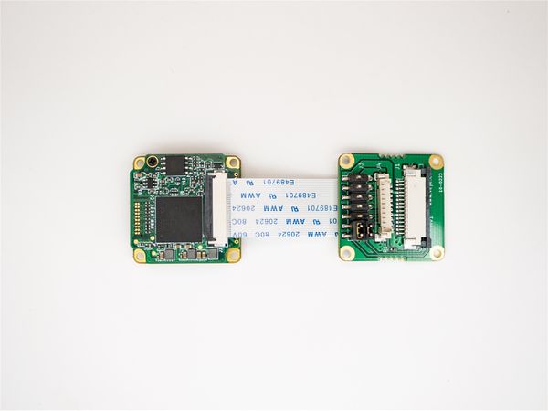
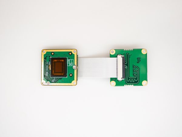
The two are connected using 0.5 mm pitch*30P FFC cable with Opposite-side contacts. The cable must be inserted with the silver contacts facing outside.
| TOP | BOTTOM |
|---|---|
2.1.2 Power supply
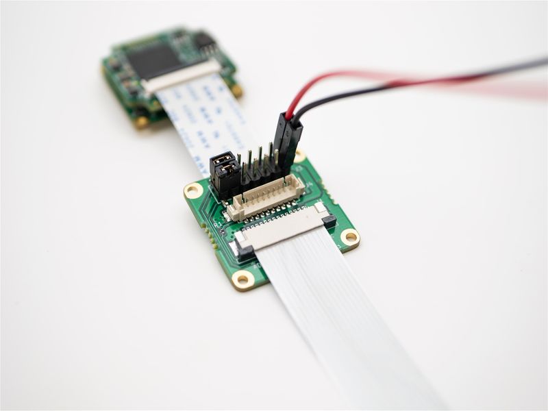
The ADP-MV1 requires a separate 5V power supply and can be powered directly from the Jetson board using a Dupont cable.
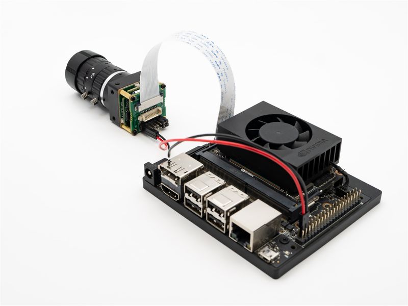
2.1.3 Connection with Nano and NX using ADP-MV1
The Nano Series and NX Series are connected in this way.
2.1.4 Connection with Orin Nano and NX using ADP-MV1
Use a 15P to 22 pin FFC Cable with the Same-side contacts. Pay attention to the direction of the contact surface.
2.2 MV series cameras use the ADP-N4 connection
2.2.1 Connection of MV series cameras and ADP-N4
The two are connected using 0.5 mm pitch*30P FFC cable with Same-side contacts. The cable must be inserted with the silver contacts facing outside.
2.2.2 Power supply
The ADP-N4 requires power supply. It supports two types of power supply, any one of them will work.
- 5V DC is connected to J19-9, which can be powered directly from the Jetson motherboard using a DuPont cable.
- 12V DC is connected to J11, which needs to be powered by an external adapter.
2.2.3 Connection with TX2 Devkit and AGX Series using ADP-N4
2.3 RAW series cameras directly connected to the Jetson Board
2.3.1 Connect to Nano or Xavier NX
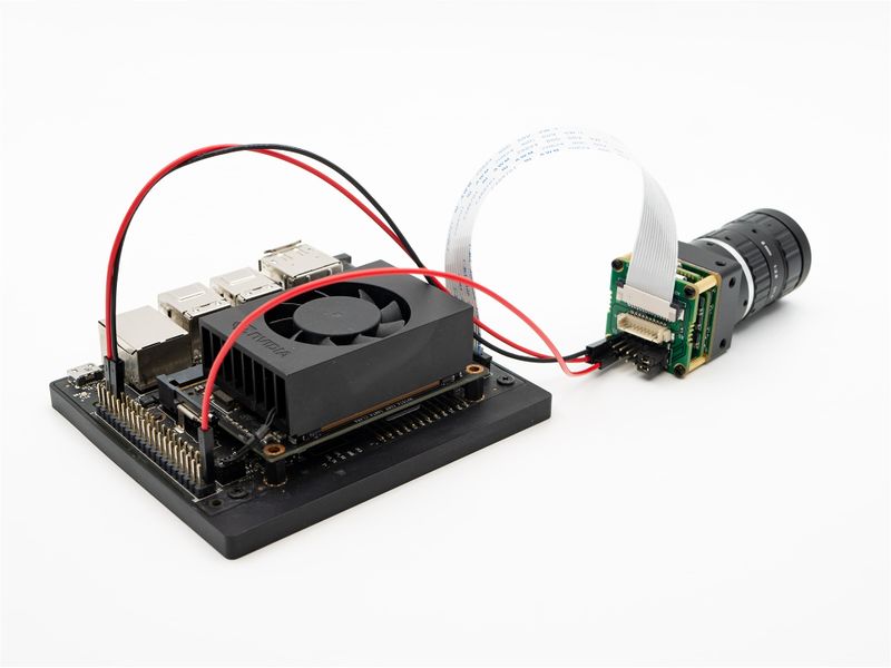
The RAW-MIPI-SC132M use a 15-pin opposite-side FFC cable, while other RAW series cameras use a 15-to-22-pin same-side FFC cable.
2.3.2 Connet to Orin Nano or Orin NX
The RAW-MIPI-SC132M use a 15-to-22-pin same-side FFC cable, while other RAW series cameras use a 22-pin opposite-side FFC cable.
2.4 RAW series cameras use the ADP-N5 connection
2.4.1 Connection of RAW series cameras and ADP-N5
The RAW-MIPI-SC132M use a 15-pin opposite-side FFC cable, while other RAW series cameras use a 15-to-22-pin same-side FFC cable.
2.4.2 Connection with TX2 Devkit and AGX Series using ADP-N5
2.5 V-by-One-HS-KIT Camera Connection Diagram
3 Upgrade Jetson system
This section describes how to upgrade the Jetson system to support MV camera module. For OS update method, please refer to Update Jetson OS.
Specially, for MV series camera, besides adding the camera driver in Linux system, we also add a kernel patch - veye_mv_l4t_<version>.patch. We provide compiled Image files.
This patch has two features:
- Added support for both Y10 and Y12 data formats for Mono cameras.
- Added support for trigger mode.
4 Description of raw data image format
On TX2 and XAVIER, 10 bit depth and 12 bit depth raw data is stored in memory in a format that is not compliant with the V4L2 standard. We have extended the definition in the linux kernel to support this case.
TY10, TY12, XY10 and XY12 are the new types we have added.
4.1 Nano
| Depth | Bit order | FourCC | Enumerator |
|---|---|---|---|
| 8 | B7 B6 B5 B4 B3 B2 B1 B0 | GREY | V4L2_PIX_FMT_GREY |
| 10 | 0 0 0 0 0 0 B9 B8 B7 B6 B5 B4 B3 B2 B1 B0 | 'Y10 ' | V4L2_PIX_FMT_Y10 |
| 12 | 0 0 0 0 B11 B10 B9 B8 B7 B6 B5 B4 B3 B2 B1 B0 | 'Y12 ' | V4L2_PIX_FMT_Y12 |
4.2 TX2
| Depth | Bit order (X is undefined) | FourCC | Enumerator |
|---|---|---|---|
| 8 | B7 B6 B5 B4 B3 B2 B1 B0 | GREY | V4L2_PIX_FMT_GREY |
| 10 | 0 0 B9 B8 B7 B6 B5 B4 B3 B2 B1 B0 X X X X | TY10 | V4L2_PIX_FMT_TX2_Y10 |
| 12 | 0 0 B11 B10 B9 B8 B7 B6 B5 B4 B3 B2 B1 B0 X X | TY12 | V4L2_PIX_FMT_TX2_Y12 |
4.3 XAVIER and Orin
| Depth | Bit order (X is undefined) | FourCC | Enumerator |
|---|---|---|---|
| 8 | B7 B6 B5 B4 B3 B2 B1 B0 | GREY | V4L2_PIX_FMT_GREY |
| 10 | 0 B9 B8 B7 B6 B5 B4 B3 B2 B1 B0 X X X X X | XY10 | V4L2_PIX_FMT_XAVIER_Y10 |
| 12 | 0 B11 B10 B9 B8 B7 B6 B5 B4 B3 B2 B1 B0 X X X | XY12 | V4L2_PIX_FMT_XAVIER_Y12 |
Also, we provide tool software in order to convert these special data formats to standard formats: https://github.com/veyeimaging/pixel_layer_convert.
We recommend using vooya as the player.
4.4 Support for trigger mode
The default driver for Jetson systems only supports video streaming mode. In its VI driver, the data reception function has a timeout mechanism. We have added a settable vi_time_out_disable option to dynamically turn this timeout mechanism on and off.
Refer to the following application example for specific applications.
5 Check system status
After system update, reboot the Jetson board.
During the Jetson system boot process, it detects the presence of cameras on all i2c buses and generates the /dev/videoX device node if it exists.
Execute the following command on the Jetson board to check if the camera is properly connected.
dmesg | grep mvcam
You can see the camera model and the camera version number probed.
A prompt as below indicates that the MV-MIPI-IMX178M camera is detected on the i2c-10 bus.
mvcam 10-003b: camera is: MV-MIPI-IMX178M
mvcam 10-003b: firmware version: 0x1080103
5.1 /dev/videoX node
The camera module is mapped as /dev/videoX device node in the Jetson system.
During the OS boot process, the cameras are detected in the order of the i2c bus. The X value is incremented from 0 according to the logical order of detection.
For instance, if only one camera is connected, X is 0 regardless of the location to which the hardware is connected. If 5 cameras are connected, X is [0-4] according to i2c bus from smallest to largest.
The v4l2-ctl command uses -d /dev/videoX to access different cameras.
In gstreamer, v4l2src can access different cameras by specifying device=/dev/videoX.
6 Configuring global variables
For the convenience of later descriptions, global variables are configured here according to the sensor size.
- MV-MIPI-IMX178M
export WIDTH=3088
export HEIGHT=2064
export FPS=22
- MV-MIPI-SC130M
export WIDTH=1280
export HEIGHT=1024
export FPS=108
- MV-MIPI-IMX296M
export WIDTH=1440
export HEIGHT=1088
export FPS=60
- MV-MIPI-IMX265M
export WIDTH=2048
export HEIGHT=1544
export FPS=45
- MV-MIPI-IMX264M
export WIDTH=2432
export HEIGHT=2056
export FPS=28
- MV-MIPI-IMX287M
export WIDTH=704
export HEIGHT=544
export FPS=319
- RAW-MIPI-SC132M
export WIDTH=1080
export HEIGHT=1280
export FPS=120
- RAW-MIPI-IMX462M
export WIDTH=1920
export HEIGHT=1080
export FPS=60
- RAW-MIPI-AR0234M
export WIDTH=1920
export HEIGHT=1200
export FPS=60
7 v4l2-ctl Application examples
7.1 Install v4l2-utils
sudo apt-get install v4l-utils
7.2 Configure parameters using v4l2-ctl
7.2.1 List the data formats supported by the camera
v4l2-ctl --list-formats-ext
The following is an example of MV-MIPI-IMX178M in the XAVIER system.
ioctl: VIDIOC_ENUM_FMT
Index : 0
Type : Video Capture
Pixel Format: 'UYVY'
Name : UYVY 4:2:2
Size: Discrete 3088x2064
Interval: Discrete 0.045s (22.000 fps)
Index : 1
Type : Video Capture
Pixel Format: 'NV16'
Name : Y/CbCr 4:2:2
Size: Discrete 3088x2064
Interval: Discrete 0.045s (22.000 fps)
Index : 2
Type : Video Capture
Pixel Format: 'GREY'
Name : 8-bit Greyscale
Size: Discrete 3088x2064
Interval: Discrete 0.045s (22.000 fps)
Index : 3
Type : Video Capture
Pixel Format: 'XY10'
Name : XAVIER 10-bit/16-bit Greyscale
Size: Discrete 3088x2064
Interval: Discrete 0.045s (22.000 fps)
Index : 4
Type : Video Capture
Pixel Format: 'XY12'
Name : XAVIER 12-bit/16-bit Greyscale
Size: Discrete 3088x2064
Interval: Discrete 0.045s (22.000 fps)
It should be noted that the UYVY and NV16 modes provided by the MV series cameras are for debugging purposes only and the maximum width cannot exceed 2880.
7.2.2 List the configurable parameters of the camera implemented in the driver
v4l2-ctl -L
User Controls
trigger_mode 0x00981901 (int) : min=0 max=2 step=1 default=0 value=0 flags=volatile, execute-on-write
trigger_src 0x00981902 (int) : min=0 max=1 step=1 default=1 value=1 flags=volatile, execute-on-write
soft_trgone 0x00981903 (button) : flags=write-only, execute-on-write
frame_rate 0x00981904 (int) : min=1 max=22 step=1 default=22 value=22 flags=volatile, execute-on-write
roi_x 0x00981905 (int) : min=0 max=2712 step=8 default=0 value=0
roi_y 0x00981906 (int) : min=0 max=1744 step=4 default=0 value=0
Camera Controls
low_latency_mode 0x009a206d (bool) : default=0 value=0
preferred_stride 0x009a206e (int) : min=0 max=65535 step=1 default=0 value=0
vi_time_out_disable 0x009a2078 (bool) : default=0 value=0
Parameters can be set and get using the following methods.
v4l2-ctl --set-ctrl [ctrl_type]=[val]
v4l2-ctl --get-ctrl [ctrl_type]
All the above functions can be implemented using mv_mipi_i2c.sh.
None of the above parameters can be modified in the state when the image acquisition is started.
Each of them is described below:
7.2.3 Trigger Mode
v4l2-ctl --set-ctrl trigger_mode=[0-2]
0:Video streaming mode
1:Normal trigger mode.
2:High-speed continuous trigger mode.
7.2.4 Trigger Source
v4l2-ctl --set-ctrl trigger_src=[0-1]
0: Software trigger mode.
1: Hardware trigger mode.
7.2.5 Software trigger command
v4l2-ctl --set-ctrl soft_trgone=1
7.2.6 Set frame rate
v4l2-ctl --set-ctrl frame_rate=[1-max]
The maximum frame rate is automatically updated as the resolution changed.
7.2.7 Set ROI and pixel format
For example:
v4l2-ctl --set-ctrl roi_x=0
v4l2-ctl --set-ctrl roi_y=0
v4l2-ctl --set-fmt-video=width=$WIDTH,height=$HEIGHT,pixelformat=GREY
The maximum frame rate will be adjusted automatically after setting ROI. Please note that the camera ROI parameters need to comply with the requirements in the camera manual.
7.2.8 preferred_stride
The preferred_stride refers to the memory size required for one line of image data. Image data for the Jetson platform is stored unpacked, i.e., one pixel occupies two bytes in the 10-bit depth and 12-bit depth data formats.
- In the normal case, the buffer needs to be 64 bytes aligned.
preferred_stride= ALIGN_UP(width*bytes_per_pixel,64)
For instance, if the width is 3088:
8bit depth,preferred_stride=3136;
10bit depth,preferred_stride=6208;
12bit depth,preferred_stride=6208;
- If VIC buffer is used, 256 bytes alignment is required.
preferred_stride= ALIGN_UP(width*bytes_per_pixel,256)
7.3 Video Streaming mode
7.3.1 Set ROI and format
Take set ROI to sensor size as an example.
v4l2-ctl --set-ctrl roi_x=0
v4l2-ctl --set-ctrl roi_y=0
v4l2-ctl --set-fmt-video=width=$WIDTH,height=$HEIGHT,pixelformat=GREY
v4l2-ctl --set-ctrl frame_rate=$FPS
7.3.2 Frame rate statistics
In streaming mode, the following commands can be used for frame rate statistics.
v4l2-ctl --set-fmt-video=width=$WIDTH,height=$HEIGHT,pixelformat=GREY --stream-mmap --stream-count=-1 --stream-to=/dev/null
7.3.3 Save image to file
7.3.3.1 MV-MIPI-IMX178M
- raw8
v4l2-ctl -d /dev/video0 --set-ctrl preferred_stride=3136
v4l2-ctl -d /dev/video0 --set-fmt-video=width=3088,height=2064,pixelformat=GREY --stream-mmap --stream-count=1 --stream-to=y8-3136x2064.raw
- raw10
v4l2-ctl -d /dev/video0 --set-ctrl preferred_stride=6208
v4l2-ctl -d /dev/video0 --set-fmt-video=width=3088,height=2064,pixelformat=XY10 --stream-mmap --stream-count=1 --stream-to=y10-3104x2064.raw
- raw12
v4l2-ctl -d /dev/video0 --set-ctrl preferred_stride=6208
v4l2-ctl -d /dev/video0 --set-fmt-video=width=3088,height=2064,pixelformat=XY12 --stream-mmap --stream-count=1 --stream-to=y12-3104x2064.raw
7.3.3.2 MV-MIPI-SC130M
Since the width 1280 of SC130 is an integer multiple of 64 and 256, there is no need to set the preferred_stride.
- raw8
v4l2-ctl -d /dev/video0 --set-fmt-video=width=1280,height=1024,pixelformat=GREY --stream-mmap --stream-count=1 --stream-to=y8-1280x1024.raw
- raw10
v4l2-ctl -d /dev/video0 --set-fmt-video=width=1280,height=1024,pixelformat=XY10 --stream-mmap --stream-count=1 --stream-to=y10-1280x1024.raw
7.3.3.3 MV-MIPI-IMX296M
- raw8
v4l2-ctl -d /dev/video0 --set-ctrl preferred_stride=1472
v4l2-ctl --set-fmt-video=width=1440,height=1088,pixelformat=GREY --stream-mmap --stream-count=1 --stream-to=y8-1472x1088.raw
- raw10
v4l2-ctl --set-fmt-video=width=1440,height=1088,pixelformat=XY10 --stream-mmap --stream-count=1 --stream-to=y10-1440x1088.raw
7.3.3.4 MV-MIPI-IMX265M
- raw8
v4l2-ctl -d /dev/video0 --set-fmt-video=width=2048,height=1544,pixelformat=GREY --stream-mmap --stream-count=1 --stream-to=y8-2048x1544.raw
- raw10
v4l2-ctl -d /dev/video0 --set-fmt-video=width=2048,height=1544,pixelformat=XY10 --stream-mmap --stream-count=1 --stream-to=y10-2048x1544.raw
- raw12
v4l2-ctl -d /dev/video0 --set-fmt-video=width=2048,height=1544,pixelformat=XY12 --stream-mmap --stream-count=1 --stream-to=y12-2048x1544.raw
7.3.3.5 MV-MIPI-IMX264M
- raw8
v4l2-ctl -d /dev/video0 --set-fmt-video=width=2432,height=2056,pixelformat=GREY --stream-mmap --stream-count=1 --stream-to=y8-2432x2056.raw
- raw10
v4l2-ctl -d /dev/video0 --set-fmt-video=width=2432,height=2056,pixelformat=XY10 --stream-mmap --stream-count=1 --stream-to=y10-2432x2056.raw
- raw12
v4l2-ctl -d /dev/video0 --set-fmt-video=width=2432,height=2056,pixelformat=XY12 --stream-mmap --stream-count=1 --stream-to=y12-2432x2056.raw
7.3.3.6 RAW-MIPI-SC132M
- raw8
v4l2-ctl -d /dev/video0 --set-ctrl preferred_stride=1088
v4l2-ctl -d /dev/video0 --set-fmt-video=width=1080,height=1280,pixelformat=GREY --stream-mmap --stream-count=1 --stream-to=y8-1088x1280.raw
- raw10
v4l2-ctl -d /dev/video0 --set-fmt-video=width=1080,height=1280,pixelformat=XY10 --stream-mmap --stream-count=1 --stream-to=y10-1080x1280.raw
7.3.3.7 MV-MIPI-IMX287M
- raw8
v4l2-ctl -d /dev/video0 --set-fmt-video=width=704,height=544,pixelformat=GREY --stream-mmap --stream-count=1 --stream-to=y8-704x544.raw
- raw10
v4l2-ctl -d /dev/video0 --set-fmt-video=width=704,height=544,pixelformat=XY10 --stream-mmap --stream-count=1 --stream-to=y10-704x544.raw
- raw12
v4l2-ctl -d /dev/video0 --set-fmt-video=width=704,height=544,pixelformat=XY12 --stream-mmap --stream-count=1 --stream-to=y12-704x544.raw
7.3.3.8 RAW-MIPI-AR0234M
- raw8
v4l2-ctl -d /dev/video0 --set-fmt-video=width=1920,height=1200,pixelformat=GREY --stream-mmap --stream-count=1 --stream-to=y8-1920x1200.raw
- raw10
v4l2-ctl -d /dev/video0 --set-fmt-video=width=1920,height=1200,pixelformat=XY10 --stream-mmap --stream-count=1 --stream-to=y10-1920x1200.raw
7.3.3.9 RAW-MIPI-IMX462M
- raw10
v4l2-ctl -d /dev/video0 --set-fmt-video=width=1920,height=1088,pixelformat=XY10 --stream-mmap --stream-count=1 --stream-to=y10-1920x1088.raw
- raw12
v4l2-ctl -d /dev/video0 --set-fmt-video=width=1920,height=1088,pixelformat=XY12 --stream-mmap --stream-count=1 --stream-to=y12-1920x1088.raw
For the image format, please refer to the section above: Description of raw data image format.
7.3.4 Preview
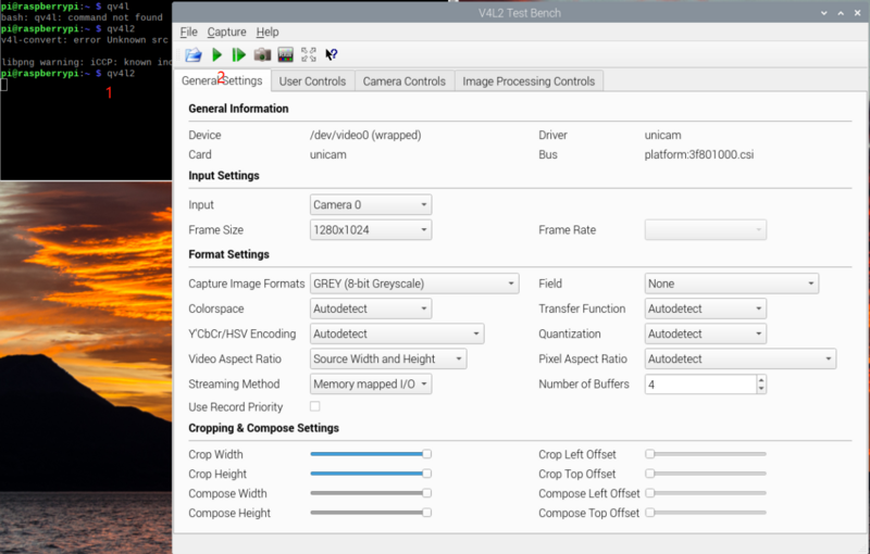
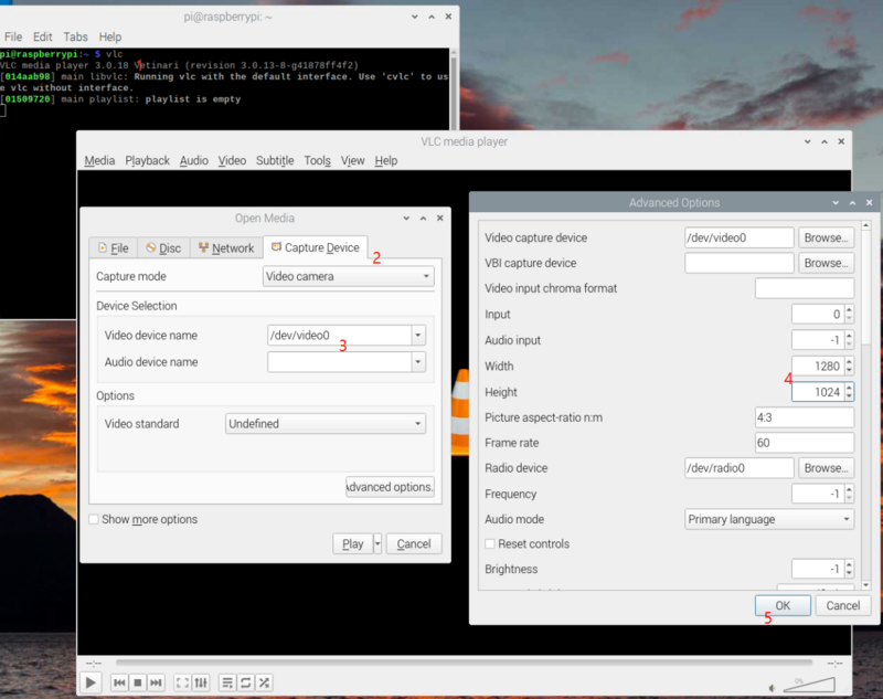
For cameras that support the GREY format, you can use qv4l2 or VLC for video preview.
7.3.4.1 Preview using qv4l2
Install qv4l2,
sudo apt install qv4l2
1. Open VLC with command line vlc to launch.
2. Hit the ▶(Play) button to call the open media window.
7.3.4.2 Preview using VLC
Install vlc,
sudo apt-get install vlc
1. Open VLC with command line vlc , or click the icon to launch.
2. Hit the ▶(Play) button to call the open media window.
3. In Capture Device >> Device Selection >> Video device name, select the camera video node.
4. Hit Advanced Options... button
5. Type in the width and height, for example, 1280 and 1024.
6. Hit OK to save the settings and see the video feed.
7.3.4.3 Preview UYVY format images using gstreamer
Note: To increase the maximum frame rate and bandwidth, some modules no longer support the UYVY format. Please use the "fmtcap" command in the script to read the registers to confirm the specific configuration.
The camera can be previewed in real time using the following command:
export DISPLAY=:0
- MV-MIPI-IMX178M
v4l2-ctl -d /dev/video0 --set-fmt-video=width=2816,height=2064,pixelformat=UYVY
gst-launch-1.0 v4l2src device=/dev/video0 ! "video/x-raw,format=(string)UYVY, width=(int)2816, height=(int)2064, framerate=(fraction)22/1" ! nvvidconv ! "video/x-raw(memory:NVMM),format=(string)I420" ! nv3dsink sync=false
The maximum width supported by UYVY mode is 2880.
- MV-MIPI-SC130M, MV-MIPI-IMX296M, MV-MIPI-IMX265M,MV-MIPI-IMX264M,MV-MIPI-IMX287M
v4l2-ctl -d /dev/video0 --set-fmt-video=width=$WIDTH,height=$HEIGHT,pixelformat=UYVY
v4l2-ctl -d /dev/video0 --set-ctrl frame_rate=$FPS
gst-launch-1.0 v4l2src device=/dev/video0 ! "video/x-raw,format=(string)UYVY, width=(int)$WIDTH, height=(int)$HEIGHT, framerate=(fraction)$FPS/1" ! nvvidconv ! "video/x-raw(memory:NVMM),format=(string)I420" ! nv3dsink sync=false
7.3.4.4 Preview GREY format images using opencv
sudo apt install python3-opencv
- Preview using this sample:
python ./v4l2dev_2_opencv_show_grey.py --roix 0 --roiy 0 --width 640 --height 480 --fps 30
7.4 Trigger mode
7.4.1 Prepare
v4l2-ctl --set-ctrl roi_x=0
v4l2-ctl --set-ctrl roi_y=0
v4l2-ctl --set-ctrl low_latency_mode=1
v4l2-ctl --set-fmt-video=width=$WIDTH,height=$HEIGHT,pixelformat=GREY
Set proper preferred_stride if necessary.
For MV-MIPI-IMX178M,3088*2064:
v4l2-ctl -d /dev/video0 --set-ctrl preferred_stride=3136
For MV-MIPI-IMX296M,1440*1088:
v4l2-ctl -d /dev/video0 --set-ctrl preferred_stride=1472
7.4.2 Software trigger mode
7.4.2.1 Set mode
v4l2-ctl --set-ctrl trigger_mode=1
v4l2-ctl --set-ctrl trigger_src=0
v4l2-ctl --set-ctrl vi_time_out_disable=1
7.4.2.2 Start acquisition
- MV-MIPI-IMX178M
v4l2-ctl --set-fmt-video=width=$WIDTH,height=$HEIGHT,pixelformat=GREY --stream-mmap --stream-count=-1 --stream-to=y8-3104x2064.raw
- MV-MIPI-SC130M
v4l2-ctl --set-fmt-video=width=1280,height=1024,pixelformat=GREY --stream-mmap --stream-count=-1 --stream-to=y8-1280x1024.raw
- MV-MIPI-IMX296M
v4l2-ctl --set-fmt-video=width=1440,height=1088,pixelformat=GREY --stream-mmap --stream-count=-1 --stream-to=y8-1472x1088.raw
- MV-MIPI-IMX265M
v4l2-ctl -d /dev/video0 --set-fmt-video=width=2048,height=1544,pixelformat=GREY --stream-mmap --stream-count=-1 --stream-to=y8-2048x1544.raw
- MV-MIPI-IMX264M
v4l2-ctl -d /dev/video0 --set-fmt-video=width=2432,height=2048,pixelformat=GREY --stream-mmap --stream-count=-1 --stream-to=y8-2432x2048.raw
- RAW-MIPI-SC132M
v4l2-ctl --set-fmt-video=width=1080,height=1280,pixelformat=GREY --stream-mmap --stream-count=-1 --stream-to=y8-1080x1280.raw
- MV-MIPI-IMX287M
v4l2-ctl -d /dev/video0 --set-fmt-video=width=704,height=544,pixelformat=GREY --stream-mmap --stream-count=-1 --stream-to=y8-704x544.raw
- RAW-MIPI-AR0234M
v4l2-ctl -d /dev/video0 --set-fmt-video=width=1920,height=1200,pixelformat=GREY --stream-mmap --stream-count=-1 --stream-to=y8-1920x1200.raw
- RAW-MIPI-IMX462M
v4l2-ctl -d /dev/video0 --set-fmt-video=width=1920,height=1088,pixelformat=XY10 --stream-mmap --stream-count=-1 --stream-to=y8-1920x1088.raw
7.4.2.3 Perform soft trigger operation
In other shell terminals, you can execute the following command multiple times for multiple triggers.
v4l2-ctl --set-ctrl soft_trgone=1
7.4.2.4 Stop triggering and capturing
Since the kernel driver is waiting for new images, you need to cancel vi_time_out_disable before exiting the acquisition operation.
v4l2-ctl --set-ctrl vi_time_out_disable=0
In the terminal of the acquisition command, press Ctrl+C to exit the acquisition operation.
7.4.3 Hardware trigger mode
To use jetson-gpio for trigger operation, please install and configure jetson-gpio first.
The following is an example of using jetson GPIO40 (Board number) as the trigger source and rising edge triggering.
You can use the mv_mipi_i2c.sh script to set other trigger parameters.
7.4.3.1 Hardware Connection
- Using ADP-MV1
- Using ADP-N4
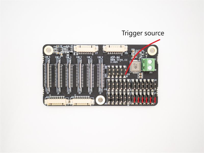
If a common trigger source connection is used, J7 is first shorted in pairs, and then connect the jetson GPIO40 to J19-1.
If the independent trigger source connection is used, the GPIO40 is directly connected to J7-1 ---- J7-11.
7.4.3.2 Set mode
v4l2-ctl --set-ctrl trigger_mode=1
v4l2-ctl --set-ctrl trigger_src=1
v4l2-ctl --set-ctrl vi_time_out_disable=1
7.4.3.3 Start acquisition
- MV-MIPI-IMX178M
v4l2-ctl --set-fmt-video=width=3088,height=2064,pixelformat=GREY --stream-mmap --stream-count=-1 --stream-to=y8-3104x2064.raw
- MV-MIPI-SC130M
v4l2-ctl --set-fmt-video=width=1280,height=1024,pixelformat=GREY --stream-mmap --stream-count=-1 --stream-to=y8-1280x1024.raw
7.4.3.4 Perform hardware trigger operation
python gpio_trigger_jetson.py
Note: script link.
7.4.3.5 Stop triggering and capturing
Since the kernel driver is waiting for new images, you need to cancel vi_time_out_disable before exiting the acquisition operation.
v4l2-ctl --set-ctrl vi_time_out_disable=0
In the terminal of the acquisition command, press Ctrl+C to exit the acquisition operation.
8 Application demo
8.1 v4l2grab_mvcam_jetson
v4l2grab_mvcam is a sample developed in C language, supporting stream mode and trigger mode.
Please refer to:https://github.com/veyeimaging/nvidia_jetson_veye_bsp/tree/master/mv_tools_jetson/examples/v4l2grab_mvcam
8.2 yavta(Video Streaming mode only)
8.2.1 install yavta
git clone https://github.com/veyeimaging/yavta.git
cd yavta;make
8.2.2 Set ROI and format
Take MV-MIPI-IMX178M, 3088*2064 as an example.
v4l2-ctl --set-ctrl roi_x=0
v4l2-ctl --set-ctrl roi_y=0
8.2.3 Save image to file
8.2.3.1 MV-MIPI-IMX178M
- raw8
v4l2-ctl -d /dev/video0 --set-ctrl preferred_stride=3136
./yavta -c1 -Fy8-3136x2064.raw --skip 0 -f Y8 -s 3088x2064 /dev/video0
- raw10
Take XAVIER as example.
v4l2-ctl -d /dev/video0 --set-ctrl preferred_stride=6208
./yavta -c1 -Fy10-3104x2064.raw --skip 0 -f XY10 -s 3088x2064 /dev/video0
- raw12
Take XAVIER as example.
v4l2-ctl -d /dev/video0 --set-ctrl preferred_stride=6208
./yavta -c1 -Fy12-3104x2064.raw --skip 0 -f XY12 -s 3088x2064 /dev/video0
8.2.3.2 MV-MIPI-SC130M
- raw8
./yavta -c1 -Fy8-1280x1024.raw --skip 0 -f Y8 -s 1280x1024 /dev/video0
- raw10
Take XAVIER as example.
./yavta -c1 -Fy10-1280x1024.raw --skip 0 -f XY10 -s 1280x1024 /dev/video0
8.2.3.3 MV-MIPI-IMX296M
- raw8
v4l2-ctl -d /dev/video0 --set-ctrl preferred_stride=1472
./yavta -c1 -Fy8-1472x1024.raw --skip 0 -f Y8 -s 1440x1088 /dev/video0
- raw10
Take XAVIER as example.
./yavta -c1 -Fy10-1440x1024.raw --skip 0 -f XY10 -s 1440x1088 /dev/video0
8.2.3.4 MV-MIPI-IMX265M
- raw8
./yavta -c1 -Fy8-2048x1544.raw --skip 0 -f Y8 -s 2048x1544 /dev/video0
- raw10
Take XAVIER as example.
./yavta -c1 -Fy10-2048x1544.raw --skip 0 -f XY10 -s 2048x1544 /dev/video0
- raw12
Take XAVIER as example.
./yavta -c1 -Fy12-2048x1544.raw --skip 0 -f XY12 -s 2048x1544 /dev/video0
8.2.3.5 MV-MIPI-IMX264M
- raw8
./yavta -c1 -Fy8-2432x2048.raw --skip 0 -f Y8 -s 2432x2048 /dev/video0
- raw10
Take XAVIER as example.
./yavta -c1 -Fy10-2432x2048.raw --skip 0 -f XY10 -s 2432x2048 /dev/video0
- raw12
Take XAVIER as example.
./yavta -c1 -Fy12-2432x2048.raw --skip 0 -f XY12 -s 2432x2048 /dev/video0
8.2.3.6 RAW-MIPI-SC132M
- raw8
./yavta -c1 -Fy8-1080x1280.raw --skip 0 -f Y8 -s 1080x1280 /dev/video0
- raw10
Take XAVIER as example.
./yavta -c1 -Fy10-1080x1280.raw --skip 0 -f XY10 -s 1080x1280 /dev/video0
8.2.3.7 MV-MIPI-IMX287M
- raw8
./yavta -c1 -Fy8-704x544.raw --skip 0 -f Y8 -s 704x544 /dev/video0
- raw10
Take XAVIER as example.
./yavta -c1 -Fy10-704x544.raw --skip 0 -f XY10 -s 704x544 /dev/video0
- raw12
Take XAVIER as example.
./yavta -c1 -Fy12-704x544.raw --skip 0 -f XY12 -s 704x544 /dev/video0
8.2.3.8 RAW-MIPI-AR0234M
- raw8
./yavta -c1 -Fy8-1920x1200.raw --skip 0 -f Y8 -s 1920x1200 /dev/video0
- raw10
Take XAVIER as example.
./yavta -c1 -Fy10-1920x1200.raw --skip 0 -f XY10 -s 1920x1200 /dev/video0
8.2.3.9 RAW-MIPI-IMX462M
Take XAVIER as example.
- raw12
./yavta -c1 -Fy12-1920x1088.raw --skip 0 -f XY12 -s 1920x1088 /dev/video0
- raw10
./yavta -c1 -Fy10-1920x1088.raw --skip 0 -f XY10 -s 1920x1088 /dev/video0
For the image format, please refer to the section above: Description of raw data image format.
9 i2c script for parameter configuration
We provide shell scripts to configure the parameters.
10 References
11 Document History
- 2023-08-16
Add support for RAW-MIPI-IMX462M and RAW-MIPI-AR0234M.
- 2023-07-31
Support V-by-One.
- 2023-04-27
Support Jetpack5.1.1.
- 2023-04-16
Remove flip function.
- 2023-03-29
Add opencv samples.
- 2023-03-37
Add description about MV-MIPI-IMX287M.
- 2023-02-22
Support Jetpack5.1
- 2022-12-11
Add description about MV-MIPI-IMX264M.
- 2022-10-14
Add description about MV-MIPI-IMX296M and MV-MIPI-IMX265M.
- 2022-08-31
Support Jetpack5.0.2
- 2022-06-23
Add ADP-N4 related descriptions.
- 2022-05-20
Release 1st version.
