|
|
| (17 intermediate revisions by 2 users not shown) |
| Line 4: |
Line 4: |
| | The MV series and RAW series cameras are cameras designed for AI applications in the industrial field. They use the MIPI CSI-2 interface and are particularly suitable for use with embedded computing platforms. They have rich data formats and triggering features, extremely low latency, high bandwidth, and reliable stability. | | The MV series and RAW series cameras are cameras designed for AI applications in the industrial field. They use the MIPI CSI-2 interface and are particularly suitable for use with embedded computing platforms. They have rich data formats and triggering features, extremely low latency, high bandwidth, and reliable stability. |
| | | | |
| − | This article takes Radxa's ZERO 3W board as an example to introduce how to connect MV and RAW series cameras to the RK3566/3K3568 system. | + | This article takes Radxa's ZERO 3W/3E board as an example to introduce how to connect MV and RAW series cameras to the RK3566/3K3568 system. |
| | | | |
| | We provide drivers for the Linux operating system (using Radxa OS Debainas an example). | | We provide drivers for the Linux operating system (using Radxa OS Debainas an example). |
| Line 35: |
Line 35: |
| | |MV series | | |MV series |
| | |MV-MIPI-IMX264M | | |MV-MIPI-IMX264M |
| | + | |Done |
| | + | |- |
| | + | |MV series |
| | + | |MV-MIPI-GMAX4002M |
| | |Done | | |Done |
| | |- | | |- |
| Line 47: |
Line 51: |
| | |RAW series | | |RAW series |
| | |RAW-MIPI-AR0234M | | |RAW-MIPI-AR0234M |
| | + | |Done |
| | + | |- |
| | + | |RAW series |
| | + | |RAW-MIPI-SC535M |
| | |Done | | |Done |
| | |} | | |} |
| | ===Hardware Setup=== | | ===Hardware Setup=== |
| − | ====Connection of MV series camera and Radxa ZERO 3W==== | + | ====Connection of MV series camera and Radxa ZERO 3W/3E==== |
| − | The MV series cameras require the ADP-MV1 adapter board in order to connect to the Radxa ZERO 3W board. | + | The MV series cameras require the [https://wiki.veye.cc/index.php/ADP-MV1-V2_Adapter_Board_Data_Sheet ADP-MV1-V2] adapter board in order to connect to the Radxa ZERO 3W/3E board. |
| | | | |
| − | The ADP-MV1 and Zero 3W are connected to each other using a 15 to 22P FFC cable, taking care that the silver contacts are facing outwards. | + | The ADP-MV1 and Zero 3W/3E are connected to each other using a 15 to 22P FFC cable, taking care that the silver contacts are facing outwards. |
| − | {| class="wikitable"
| + | <br /> |
| − | !TOP
| + | [[File:Radax MV.png|alt=Radxa Zero 3W/3E connect to MV camera|center|thumb|700x700px|Radxa Zero 3W/3E connect to MV camera]] |
| − | !BOTTOM
| + | <br /> |
| − | |-
| |
| − | |[[File:Radxa Zero 3W connect to MV camera.jpg|link=https://wiki.veye.cc/index.php/File:Radxa%20Zero%203W%20connect%20to%20MV%20camera.jpg|alt=|center|thumb|600x600px|Radxa Zero 3W connect to MV camera]]
| |
| − | |[[File:Radxa Zero 3W connect to MV camera 2.jpg|link=https://wiki.veye.cc/index.php/File:Radxa%20Zero%203W%20connect%20to%20MV%20camera%202.jpg|alt=|center|thumb|600x600px|Radxa Zero 3W connect to MV camera 2]]
| |
| − | |}
| |
| | =====Connection of RAW-MIPI-SC132M and ADP-MV2===== | | =====Connection of RAW-MIPI-SC132M and ADP-MV2===== |
| | The two are connected to each other using a 15 to 22P FFC cable, taking care that the silver contacts are facing outwards. | | The two are connected to each other using a 15 to 22P FFC cable, taking care that the silver contacts are facing outwards. |
| − | {| class="wikitable"
| + | <br /> |
| − | !TOP
| + | [[File:Raw-15-22pin.png|alt=Radxa Zero 3W/3E connect to RAW-MIPI-SC132M|center|thumb|700x700px|Radxa Zero 3W/3E connect to RAW-MIPI-SC132M]] |
| − | !BOTTOM
| + | <br /> |
| − | |-
| + | ====Connection of other RAW series camera and Radxa ZERO 3W/3E==== |
| − | |[[File:Radxa Zero 3W connect to RAW-MIPI-SC132M.jpg|link=https://wiki.veye.cc/index.php/File:Radxa%20Zero%203W%20connect%20to%20RAW-MIPI-SC132M.jpg|alt=|center|thumb|600x600px|Radxa Zero 3W connect to RAW-MIPI-SC132M]]
| |
| − | |[[File:Radxa Zero 3W connect to RAW-MIPI-SC132M 2.jpg|link=https://wiki.veye.cc/index.php/File:Radxa%20Zero%203W%20connect%20to%20RAW-MIPI-SC132M%202.jpg|alt=|center|thumb|600x600px|Radxa Zero 3W connect to RAW-MIPI-SC132M 2]]
| |
| − | |}
| |
| − | ====Connection of other RAW series camera and Radxa ZERO 3W==== | |
| | The two are connected using 0.5 mm pitch*pin FFC cable with opposite-side contacts. The cable must be inserted with the silver contacts facing outside. | | The two are connected using 0.5 mm pitch*pin FFC cable with opposite-side contacts. The cable must be inserted with the silver contacts facing outside. |
| − | {| class="wikitable"
| + | <br /> |
| − | !TOP
| + | [[File:Raw-22pin.png|alt=Radxa Zero 3W/3E connect to RAW series camera|center|thumb|700x700px|Radxa Zero 3W/3E connect to RAW series camera]] |
| − | !BOTTOM
| + | <br /> |
| − | |-
| |
| − | |[[File:Radxa Zero 3W connect to RAW series camera.jpg|link=https://wiki.veye.cc/index.php/File:Radxa%20Zero%203W%20connect%20to%20RAW%20series%20camera.jpg|alt=|center|thumb|600x600px|Radxa Zero 3W connect to RAW series camera]]
| |
| − | |[[File:Radxa Zero 3W connect to RAW series camera 2.jpg|link=https://wiki.veye.cc/index.php/File:Radxa%20Zero%203W%20connect%20to%20RAW%20series%20camera%202.jpg|alt=ADP-MV2 to RAW series camera No.2|center|thumb|600x600px|Radxa Zero 3W connect to RAW series camera 2]]
| |
| − | |}
| |
| | ===Introduction to github repositories=== | | ===Introduction to github repositories=== |
| | + | https://github.com/veyeimaging/rk35xx_veye_bsp |
| | + | |
| | https://github.com/veyeimaging/rk35xx_radxa | | https://github.com/veyeimaging/rk35xx_radxa |
| | | | |
| Line 95: |
Line 93: |
| | We provide a deb installation package that can be installed directly. | | We provide a deb installation package that can be installed directly. |
| | ====Burn Radxa standard system==== | | ====Burn Radxa standard system==== |
| − | Refer to the [https://wiki.t-firefly.com/en/ROC-RK3566-PC/01-bootmode.html Radxa documentation] to burn in a standard system. | + | Refer to the Radxa documentation to burn in a standard system. |
| | + | |
| | + | The installation package we are currently releasing is based on [https://github.com/radxa-build/radxa-zero3/releases/download/b6/radxa-zero3_debian_bullseye_xfce_b6.img.xz this image] version. |
| | ====Using prebuilt Image and dtb file==== | | ====Using prebuilt Image and dtb file==== |
| | Using the compiled debain installation package | | Using the compiled debain installation package |
| Line 101: |
Line 101: |
| | On the RK35xx board, | | On the RK35xx board, |
| | | | |
| − | Download the latest rk356x_Radxa_ubuntu.tar.gz from [https://github.com/veyeimaging/rk35xx_radxa/releases/ https://github.com/veyeimaging/rk35xx_Radxa/releases/] . | + | Download the latest rk356x_radxa_zero3w.tar.gz or rk356x_radxa_zero3e.tar.gz from https://github.com/veyeimaging/rk35xx_radxa/releases/ . |
| | | | |
| | <code>tar -xavf rk356x_radxa_zero3w.tar.gz</code> | | <code>tar -xavf rk356x_radxa_zero3w.tar.gz</code> |
| | | | |
| − | <code>cd rk356x_radxa_zero3w/released_images/cam2m</code> | + | <code>cd rk356x_radxa_zero3w/released_images/mvcam</code> |
| | | | |
| − | <code>sudo dpkg -i linux-headers-5.10.160-36-rk356x_5.10.160-36_arm64_cam2m.deb</code> | + | <code>sudo dpkg -i linux-headers-5.10.160-36-rk356x_5.10.160-36_arm64_mvcam.deb</code> |
| | | | |
| − | <code>sudo dpkg -i linux-image-5.10.160-36-rk356x_5.10.160-36_arm64_cam2m.deb</code> | + | <code>sudo dpkg -i linux-image-5.10.160-36-rk356x_5.10.160-36_arm64_mvcam.deb</code> |
| | | | |
| | <code>sudo reboot</code> | | <code>sudo reboot</code> |
| Line 124: |
Line 124: |
| | You can see the camera model and the camera version number probed. | | You can see the camera model and the camera version number probed. |
| | | | |
| − | A prompt as below indicates that the MV-MIPI-IMX296M camera is detected on the i2c-7 bus. | + | A prompt as below indicates that the MV-MIPI-IMX296M camera is detected on the i2c-2 bus. |
| | | | |
| − | <code>mvcam 7-003b: camera is:MV-MIPI-IMX296M</code> | + | <code>mvcam 2-003b: camera is:MV-MIPI-IMX296M</code> |
| | | | |
| − | <code>mvcam 7-003b: firmware version: 0x1290133</code> | + | <code>mvcam 2-003b: firmware version: 0x1290133</code> |
| | | | |
| − | On the ROC-RK3588S-PC, the camera is mounted on i2c-7, with an i2c address of 0x3b.
| + | For Radxa Zero 3W/3E, the camera is connected to i2c-2. |
| − | | |
| − | On the ROC-RK3566-PC, the camera is mounted on i2c-4.
| |
| | | | |
| | *Check the video0 device node: | | *Check the video0 device node: |
| Line 143: |
Line 141: |
| | | | |
| | After successfully identifying the camera, the camera will be recognized as /dev/video0. | | After successfully identifying the camera, the camera will be recognized as /dev/video0. |
| − | ====Using media-ctl to view topology====
| |
| − | Using the media-ctl command can clearly display the current topography structure.
| |
| | | | |
| − | <code>media-ctl -p -d /dev/media0</code>
| + | ===Camera Application Development Guide=== |
| − | =====Link relationship=====
| + | [[MV Camera Application Development Guide on Rochchip|Application Development Guide]] |
| − | mv camera->rockchip-csi2-dphy0->rockchip-mipi-csi2->stream_cif_mipi_id0 - - ->DDR(/dev/video0)
| |
| | | | |
| − | The application can obtain images through the /dev/video0 node.
| + | ===Compile drivers and dtb from source code=== |
| − | =====mv camera entity information===== | |
| − | Taking the MV-MIPI-IMX296M as an example:
| |
| | | | |
| − | <code>- entity 63: m00_b_mvcam 7-003b (1 pad, 1 link)</code>
| + | *RK356x |
| | | | |
| − | <code> type V4L2 subdev subtype Sensor flags 0</code>
| + | https://github.com/veyeimaging/rk35xx_radxa/tree/main/linux/drivers/rk356x |
| | + | ===i2c script for parameter configuration=== |
| | + | Because of the high degree of freedom of our camera parameters, we do not use V4L2 parameters to control, but use scripts to configure parameters. |
| | | | |
| − | <code> device node name /dev/v4l-subdev2</code>
| + | https://github.com/veyeimaging/rk35xx_radxa/tree/main/i2c_cmd |
| | | | |
| − | <code> pad0: Source</code>
| + | using -b option to identify which bus you want to use. |
| | | | |
| − | <code> [fmt:Y8_1X8/1456x1088@100/6000 field:none]</code>
| + | *VEYE series |
| | | | |
| − | <code> -> "rockchip-csi2-dphy0":0 [ENABLED]</code>
| + | Video Control Toolkits Manual :[[VEYE-MIPI-290/327 i2c/|VEYE-MIPI-327 I2C]] |
| − | | |
| − | You can see that:
| |
| − | | |
| − | *The complete name of this entity is: <code>m00_b_mvcam 7-003b</code>.(It is <code>m00_b_mvcam 4-003b</code>on ROC-RK3566-PC.)
| |
| − | *It is a V4L2 subdev (Sub-Device) Sensor.
| |
| − | *Its corresponding node is <code>/dev/v4l-subdev2</code>, which can be opened and configured by applications (such as <code>v4l2-ctl</code>).
| |
| − | *Its output format is <code>[fmt:Y8_1X8/1456x1088@100/6000 field:none]</code>, where <code>Y8_1X8</code> is a shorthand for a mbus-code, which will be listed in the next section of this article.
| |
| − | *The current resolution is <code>1456x1088</code>.
| |
| − | *The current frame interval is <code>100/6000</code>, which means the frame rate is 60.
| |
| − | *The data format output by the camera can be modified using the media-ctl command.
| |
| − | | |
| − | =====mbus-code list=====
| |
| − | MV series and RAW series cameras have different data format capabilities, which can be found in the data manual for each camera model.
| |
| − | {| class="wikitable"
| |
| − | !Format on datasheet
| |
| − | !mbus-code for media-ctl
| |
| − | !FourCC pixelformat for v4l2-ctl
| |
| − | |-
| |
| − | |RAW8
| |
| − | |Y8_1X8
| |
| − | |GREY
| |
| − | |-
| |
| − | |RAW10
| |
| − | |Y10_1X10
| |
| − | |'Y10 '
| |
| − | |-
| |
| − | |RAW12
| |
| − | |Y12_1X12
| |
| − | |'Y12 '
| |
| − | |-
| |
| − | |UYVY
| |
| − | |UYVY8_2X8
| |
| − | |UYVY
| |
| − | |}
| |
| − | ===Raw data format===
| |
| − | The VICAP module of RK3588 supports two data saving formats, Compact and Noncompact RAW. You can modify the mode using the RKCIF_CMD_SET_CSI_MEMORY_MODE ioctl command of RKCIF. By default, the output is in Compact RAW format.[[File:Compact raw and noncompact raw of rk3588 vicap.png|center|thumb|800x800px|Compact raw and noncompact raw of rk3588 VICAP|link=http://wiki.veye.cc/index.php/File:Compact_raw_and_noncompact_raw_of_rk3588_vicap.png]]
| |
| − | ====Noncompact RAW====
| |
| − | For pixel data with 10-bit depth or 12-bit depth, two bytes are always used to store one pixel. This storage method is convenient for software processing, but it has the disadvantage of occupying a large amount of space.
| |
| − | | |
| − | Depending on whether the effective data is stored in the high bits or low bits, it can be further divided into two types: high align and low align.
| |
| − | =====Noncompact RAW(high align)=====
| |
| − | Data is saved to the high bits, and the unused low bits are filled with 0. This is one of the data formats supported by RK VICAP.
| |
| − | =====Noncompact RAW(low align)=====
| |
| − | In Noncompact RAW (low align) format, data is saved to the low bits, and the unused high bits are filled with 0. The V4L2 standard 'Y10' (10-bit Greyscale) and 'Y12' (12-bit Greyscale) formats are both stored in this way.
| |
| − | | |
| − | The pixel_layer_convert conversion tool mentioned later in the article also converts Compact RAW to this storage format for easy display using image players.
| |
| − | ====Compact RAW====
| |
| − | As shown above,there is no bit padding between pixels in this storage format.
| |
| − | ====Line stride====
| |
| − | To facilitate fast operations on images, the system usually provides row-aligned buffer sizes for each line of data. RK3588 uses 256-byte alignment for this purpose.
| |
| − | | |
| − | line_stride = ALIGN_UP(image_width*bits_per_pixel/8,256)
| |
| − | | |
| − | For example, when the image width is 1456:
| |
| − | | |
| − | 8bit depth,line_stride=1536
| |
| − | | |
| − | 10bit depth,preferred_stride=2048
| |
| − | | |
| − | 12bit depth,preferred_stride=2304
| |
| − | ====Format convert tool====
| |
| − | We have written a small tool: [https://github.com/veyeimaging/pixel_layer_convert pixel_layer_convert], which can easily convert Compact images to Noncompact (low align) images.
| |
| − | | |
| − | For example, the following command can convert a Compact RAW10 image with a width of 1456 to Noncompact RAW10 format:
| |
| − | | |
| − | <code>./pixel_layer_convert -I R10C -i y10-1456x1088_0001.raw -o y10-1456x1088_0001_new.raw -w 1456</code>
| |
| − | ====Raw data image player====
| |
| − | We recommend using [https://www.offminor.de/ vooya] as the player, which supports GREY, and unpacked image formats.
| |
| − | | |
| − | Also, y8 file can be used with this player: [https://yuv-player-deluxe.software.informer.com/2.6/ YUV Displayer Deluxe].
| |
| − | ===Application examples===
| |
| − | ====Configuring global variables====
| |
| − | Based on the board model, configure the I2C_BUS global variable as follows:
| |
| − | | |
| − | *ROC-RK3588S-PC
| |
| − | | |
| − | <code>export I2C_BUS=7</code>
| |
| − | | |
| − | *ROC-RK3566-PC
| |
| − | | |
| − | <code>export I2C_BUS=4</code>
| |
| − | | |
| − | For the convenience of later descriptions, global variables are configured here according to the sensor size.
| |
| − | | |
| − | *MV-MIPI-IMX178M
| |
| − | | |
| − | <code>export WIDTH=3088</code>
| |
| − | | |
| − | <code>export HEIGHT=2064</code>
| |
| − | | |
| − | <code>export FPS=22</code>
| |
| − | | |
| − | *MV-MIPI-SC130M
| |
| − | | |
| − | <code>export WIDTH=1280</code>
| |
| − | | |
| − | <code>export HEIGHT=1024</code>
| |
| − | | |
| − | <code>export FPS=108</code>
| |
| − | | |
| − | *MV-MIPI-IMX296M
| |
| − | | |
| − | <code>export WIDTH=1456</code>
| |
| − | | |
| − | <code>export HEIGHT=1088</code>
| |
| − | | |
| − | <code>export FPS=60</code>
| |
| − | | |
| − | *MV-MIPI-IMX287M
| |
| − | | |
| − | <code>export WIDTH=704</code>
| |
| − | | |
| − | <code>export HEIGHT=544</code>
| |
| − | | |
| − | <code>export FPS=319</code>
| |
| − | | |
| − | *MV-MIPI-IMX265M
| |
| − | | |
| − | <code>export WIDTH=2048</code>
| |
| − | | |
| − | <code>export HEIGHT=1544</code>
| |
| − | | |
| − | <code>export FPS=45</code>
| |
| − | | |
| − | *MV-MIPI-IMX264M
| |
| − | | |
| − | <code>export WIDTH=2432</code>
| |
| − | | |
| − | <code>export HEIGHT=2056</code>
| |
| − | | |
| − | <code>export FPS=28</code>
| |
| − | | |
| − | *RAW-MIPI-SC132M
| |
| − | | |
| − | <code>export WIDTH=1024</code>
| |
| − | | |
| − | <code>export HEIGHT=1280</code>
| |
| − | | |
| − | <code>export FPS=120</code>
| |
| − | | |
| − | *RAW-MIPI-IMX462M
| |
| − | | |
| − | <code>export WIDTH=1920</code>
| |
| − | | |
| − | <code>export HEIGHT=1088</code>
| |
| − | | |
| − | <code>export FPS=60</code>
| |
| − | | |
| − | *RAW-MIPI-AR0234M
| |
| − | | |
| − | <code>export WIDTH=1920</code>
| |
| − | | |
| − | <code>export HEIGHT=1200</code>
| |
| − | | |
| − | <code>export FPS=60</code>
| |
| − | ====Configure parameters using v4l2-ctl====
| |
| − | <code>$ v4l2-ctl -d /dev/v4l-subdev2 -L</code>
| |
| − | | |
| − | <code>User Controls</code>
| |
| − | | |
| − | <code> trigger_mode 0x00981901 (int) : min=0 max=2 step=1 default=0 value=0 flags=volatile, execute-on-write</code>
| |
| − | | |
| − | <code> trigger_src 0x00981902 (int) : min=0 max=1 step=1 default=1 value=1 flags=volatile, execute-on-write</code>
| |
| − | | |
| − | <code> soft_trgone 0x00981903 (button) : flags=write-only, execute-on-write</code>
| |
| − | | |
| − | <code> frame_rate 0x00981904 (int) : min=1 max=60 step=1 default=60 value=60 flags=volatile, execute-on-write</code>
| |
| − | | |
| − | <code> roi_x 0x00981905 (int) : min=0 max=1376 step=8 default=0 value=0</code>
| |
| − | | |
| − | <code> roi_y 0x00981906 (int) : min=0 max=1024 step=4 default=0 value=0</code>
| |
| − | | |
| − | Parameters can be set and get using the following methods.
| |
| − | | |
| − | <code>v4l2-ctl --set-ctrl [ctrl_type]=[val]</code>
| |
| − | | |
| − | <code>v4l2-ctl --get-ctrl [ctrl_type]</code>
| |
| − | | |
| − | All the above functions can be implemented using [[Mv mipi i2c.sh user guide|mv_mipi_i2c.sh]].
| |
| − | | |
| − | Note that the above parameters cannot be modified during the capture process.
| |
| − | | |
| − | The following is an explanation of each parameter:
| |
| − | =====Trigger Mode=====
| |
| − | <code>v4l2-ctl --set-ctrl <small>trigger_mode=[0-2]</small></code>
| |
| − | | |
| − | 0:Video streaming mode
| |
| − | | |
| − | 1:Normal trigger mode.
| |
| − | | |
| − | 2:High-speed continuous trigger mode.
| |
| − | =====Trigger Source=====
| |
| − | <code>v4l2-ctl --set-ctrl <small>trigger_src=[0-1]</small></code>
| |
| − | | |
| − | 0: Software trigger mode.
| |
| − | | |
| − | 1: Hardware trigger mode.
| |
| − | =====Software trigger command=====
| |
| − | <code>v4l2-ctl --set-ctrl <small>soft_trgone=1</small></code>
| |
| − | =====Set frame rate=====
| |
| − | <code>v4l2-ctl --set-ctrl frame_rate=[1-max]</code>
| |
| − | | |
| − | The maximum frame rate is automatically updated as the resolution changed.
| |
| − | =====Set the starting position of the ROI=====
| |
| − | <code>v4l2-ctl -d /dev/v4l-subdev2 --set-ctrl roi_x=0</code>
| |
| − | | |
| − | <code>v4l2-ctl -d /dev/v4l-subdev2 --set-ctrl roi_y=0</code>
| |
| − | | |
| − | After setting the ROI starting position, you need to complete the full ROI configuration using the <code>media-ctl</code> command.
| |
| − | | |
| − | Note that setting the ROI may affect the maximum frame rate, and the ROI parameters need to meet the requirements specified in the camera manual.
| |
| − | ====Set image format using media-ctl====
| |
| − | use the following command to configure the camera's data format, resolution, and frame rate using <code>media-ctl</code>:
| |
| − | | |
| − | <code>media-ctl -d /dev/media0 --set-v4l2 '"m00_b_mvcam '"$I2C_BUS"'-003b":0[fmt:Y8_1X8/'"$WIDTH"'x'"$HEIGHT"'@1/'"$FPS"']'</code>
| |
| − | | |
| − | Among them: <code>"m00_b_mvcam '"$I2C_BUS"'-003b"</code> refers to the complete name of the camera entity, <code>Y8_1X8</code> is the mbus-code, <code>'"$WIDTH"'x'"$HEIGHT"'</code> indicates the resolution, <code>1/'"$FPS"'</code> indicates the resolution frame rate.
| |
| − | | |
| − | The width and height here cooperate with the roi_x and roi_y of the v4l2-ctl command to form the ROI parameter.
| |
| − | | |
| − | For example, for MV-MIPI-IMX296M, the command after variable replacement would be:
| |
| − | | |
| − | <code>media-ctl -d /dev/media0 --set-v4l2 '"m00_b_mvcam 7-003b":0[fmt:Y8_1X8/1456x1088@1/60 field:none]'</code>
| |
| − | | |
| − | You can not only configure the data format, resolution, and frame rate in one command, but also modify them separately as needed.
| |
| − | ====Video Streaming mode====
| |
| − | =====Set data format, resolution, frame rate=====
| |
| − | <code>v4l2-ctl -d /dev/v4l-subdev2 --set-ctrl roi_x=0</code>
| |
| − | | |
| − | <code>v4l2-ctl -d /dev/v4l-subdev2 --set-ctrl roi_y=0</code>
| |
| − | | |
| − | <code>media-ctl -d /dev/media0 --set-v4l2 '"m00_b_mvcam '"$I2C_BUS"'-003b":0[fmt:Y8_1X8/'"$WIDTH"'x'"$HEIGHT"'@1/'"$FPS"']'</code>
| |
| − | =====Frame rate statistics=====
| |
| − | In streaming mode, the following commands can be used for frame rate statistics:
| |
| − | | |
| − | <code>v4l2-ctl --set-fmt-video=width=$WIDTH,height=$HEIGHT,pixelformat=GREY --stream-mmap --stream-count=-1 --stream-to=/dev/null</code>
| |
| − | | |
| − | Or:
| |
| − | | |
| − | <code>./yavta -c1000 --skip 0 -f Y8 -s ${WIDTH}x${HEIGHT} /dev/video0</code>
| |
| − | =====Save image to file=====
| |
| − | | |
| − | *raw8
| |
| − | | |
| − | <code>v4l2-ctl -d /dev/video0 --set-fmt-video=width=$WIDTH,height=$HEIGHT,pixelformat=GREY --stream-mmap --stream-count=1 --stream-to=y8-${WIDTH}x${HEIGHT}.raw</code>
| |
| − | | |
| − | *raw10
| |
| − | | |
| − | <code>v4l2-ctl -d /dev/video0 --set-fmt-video=width=$WIDTH,height=$HEIGHT,pixelformat='Y10 ' --stream-mmap --stream-count=1 --stream-to=y10-${WIDTH}x${HEIGHT}.raw</code>
| |
| − | | |
| − | *raw12
| |
| − | | |
| − | <code>v4l2-ctl -d /dev/video0 --set-fmt-video=$WIDTH,height=$HEIGHT,pixelformat='Y12 ' --stream-mmap --stream-count=1 --stream-to=y12-${WIDTH}x${HEIGHT}.raw</code>
| |
| − | | |
| − | Please refer to the description in the previous section for the image format.
| |
| − | =====Example of yavta=====
| |
| − | ======Install yavta======
| |
| − | <code>git clone <nowiki>git://git.ideasonboard.org/yavta.git</nowiki></code>
| |
| − | | |
| − | <code>cd yavta;make</code>
| |
| − | ======Save image to file======
| |
| − | After setting data format, resolution, frame rate,run:
| |
| − | | |
| − | <code>./yavta -c1 -Fy8-${WIDTH}x${HEIGHT}.raw --skip 0 -f Y8 -s ${WIDTH}x${HEIGHT} /dev/video0</code>
| |
| − | =====Example of import image to OpenCV=====
| |
| − | <code>sudo apt install python3-opencv</code>
| |
| − | | |
| − | See the [https://github.com/veyeimaging/rk356x_firefly/tree/main/linux/samples samples] directory on github for details.
| |
| − | | |
| − | <code>python ./v4l2dev_2_opencv_show_grey.py --width 1456 --height 1088 --fps 60 --i2c 7</code>
| |
| − | =====Example of gstreamer application=====
| |
| − | To facilitate installation and debugging, the MV series cameras provide UYVY mode, which supports a maximum width of 2880 and can be previewed in real time using the following command.
| |
| − | | |
| − | Note that the RAW series does not support the UYVY format.
| |
| − | | |
| − | Note: To increase the maximum frame rate and bandwidth, some modules no longer support the UYVY format. Please use the "fmtcap" command in the script to read the registers to confirm the specific configuration.
| |
| − | | |
| − | We provide several gstreamer routines that implement the preview function. See the [https://github.com/veyeimaging/rk356x_firefly/tree/main/linux/samples samples] directory on github for details.
| |
| − | ====Trigger mode====
| |
| − | =====Set data format, resolution, frame rate=====
| |
| − | <code>v4l2-ctl -d /dev/v4l-subdev2 --set-ctrl roi_x=0</code>
| |
| − | | |
| − | <code>v4l2-ctl -d /dev/v4l-subdev2 --set-ctrl roi_y=0</code>
| |
| − | | |
| − | <code>media-ctl -d /dev/media0 --set-v4l2 '"m00_b_mvcam '"$I2C_BUS"'-003b":0[fmt:Y8_1X8/'"$WIDTH"'x'"$HEIGHT"'@1/'"$FPS"']'</code>
| |
| − | =====Software trigger mode=====
| |
| − | ======Set mode======
| |
| − | <code>v4l2-ctl -d /dev/v4l-subdev2 --set-ctrl <small>trigger_mode=1</small></code>
| |
| − | | |
| − | <code>v4l2-ctl -d /dev/v4l-subdev2 --set-ctrl <small>trigger_src=0</small></code>
| |
| − | ======Start acquisition======
| |
| − | <code>v4l2-ctl -d /dev/video0 --set-fmt-video=width=$WIDTH,height=$HEIGHT,pixelformat=GREY --stream-mmap --stream-count=1 --stream-to=y8-${WIDTH}x${HEIGHT}.raw</code>
| |
| − | ======Perform soft trigger operation======
| |
| − | In other shell terminals, you can execute the following command multiple times for multiple triggers.
| |
| − | | |
| − | <code>v4l2-ctl -d /dev/v4l-subdev2 --set-ctrl <small>soft_trgone=1</small></code>
| |
| − | =====Hardware trigger mode=====
| |
| − | ======Set mode======
| |
| − | <code>v4l2-ctl -d /dev/v4l-subdev2 --set-ctrl <small>trigger_mode=1</small></code>
| |
| − | | |
| − | <code>v4l2-ctl -d /dev/v4l-subdev2 --set-ctrl <small>trigger_src=1</small></code>
| |
| − | | |
| − | The [[Mv mipi i2c.sh user guide|mv_mipi_i2c.sh]] script can be used to set rich trigger parameters.
| |
| − | ======Start acquisition======
| |
| − | <code>v4l2-ctl -d /dev/video0 --set-fmt-video=width=$WIDTH,height=$HEIGHT,pixelformat=GREY --stream-mmap --stream-count=1 --stream-to=y8-${WIDTH}x${HEIGHT}.raw</code>
| |
| − | ======Perform hardware trigger operation======
| |
| − | Connect the appropriate trigger signal to the trigger pin of the camera and trigger it.
| |
| − | ===i2c script for parameter configuration===
| |
| − | We provide shell scripts to configure the parameters.
| |
| − | | |
| − | [[mv_mipi_i2c.sh user guide]]
| |
| − | ===Question Feedback===
| |
| − | We are committed to providing richer possibilities for image applications on embedded platforms. Therefore, our software for embedded platforms is based on the principle of open source.
| |
| − | | |
| − | If you have any questions or suggestions about our existing software, please feel free to submit them to the [http://forum.veye.cc/ forum] or email our technical staff at xumm#csoneplus.com.
| |
| | ===References=== | | ===References=== |
| | | | |
| − | *ROC-RK3566-PC Manual | + | *Radxa Zero 3W/3E Manual |
| − | | |
| − | [https://wiki.t-firefly.com/en/ROC-RK3566-PC/ https://wiki.t-Radxa.com/en/ROC-RK3566-PC/]
| |
| − | | |
| − | *ROC-RK3588S-PC Manual
| |
| | | | |
| − | [https://wiki.t-firefly.com/en/ROC-RK3588S-PC/ https://wiki.t-Radxa.com/en/ROC-RK3588S-PC/]
| + | https://docs.radxa.com/zero/zero3 |
| | | | |
| − | *Radxa Linux User Guide | + | *BSP toolkit |
| | | | |
| − | [https://wiki.t-firefly.com/en/Firefly-Linux-Guide/index.html https://wiki.t-Radxa.com/en/Radxa-Linux-Guide/index.html]
| + | https://radxa-repo.github.io/bsp/ |
| | ===Document History=== | | ===Document History=== |
| | | | |
| − | *2024-04-17 | + | *2025-12-26 |
| | | | |
| − | Support RK3566.
| + | Add a chapter on application development guidelines |
| | | | |
| − | *2024-03-10 | + | *2025-04-07 |
| | | | |
| − | Add pictures and descriptions of hardware connections for the new version of ADP-MV2. | + | Add support for Radxa Zero 3E. |
| | | | |
| − | *2023-08-30 | + | *2025-03-23 |
| | | | |
| − | Add support for RAW-MIPI-IMX462M and RAW-MIPI-AR0234M. | + | Add description of mv_probe.sh. |
| | | | |
| − | *2023-07-31 | + | *2024-07-09 |
| | | | |
| − | Support V-by-One on ubuntu system.
| + | Add support for RAW-MIPI-SC535M. |
| | | | |
| − | *2023-04-12 | + | *2024-04-24 |
| | | | |
| | Release 1st version. | | Release 1st version. |
查看中文
1 Overview
The MV series and RAW series cameras are cameras designed for AI applications in the industrial field. They use the MIPI CSI-2 interface and are particularly suitable for use with embedded computing platforms. They have rich data formats and triggering features, extremely low latency, high bandwidth, and reliable stability.
This article takes Radxa's ZERO 3W/3E board as an example to introduce how to connect MV and RAW series cameras to the RK3566/3K3568 system.
We provide drivers for the Linux operating system (using Radxa OS Debainas an example).
1.1 Camera Module List
| Series
|
Model
|
Status
|
| MV series
|
MV-MIPI-IMX178M
|
Done
|
| MV series
|
MV-MIPI-SC130M
|
Done
|
| MV series
|
MV-MIPI-IMX296M
|
Done
|
| MV series
|
MV-MIPI-IMX287M
|
Done
|
| MV series
|
MV-MIPI-IMX265M
|
Done
|
| MV series
|
MV-MIPI-IMX264M
|
Done
|
| MV series
|
MV-MIPI-GMAX4002M
|
Done
|
| RAW series
|
RAW-MIPI-SC132M
|
Done
|
| RAW series
|
RAW-MIPI-IMX462M
|
Done
|
| RAW series
|
RAW-MIPI-AR0234M
|
Done
|
| RAW series
|
RAW-MIPI-SC535M
|
Done
|
2 Hardware Setup
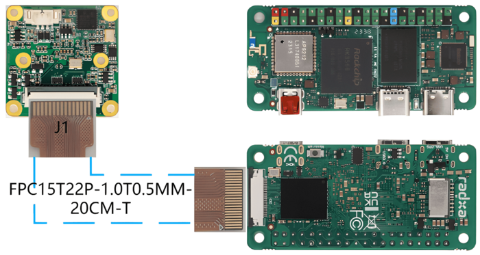
2.1 Connection of MV series camera and Radxa ZERO 3W/3E
The MV series cameras require the ADP-MV1-V2 adapter board in order to connect to the Radxa ZERO 3W/3E board.
The ADP-MV1 and Zero 3W/3E are connected to each other using a 15 to 22P FFC cable, taking care that the silver contacts are facing outwards.

Radxa Zero 3W/3E connect to MV camera
2.1.1 Connection of RAW-MIPI-SC132M and ADP-MV2
The two are connected to each other using a 15 to 22P FFC cable, taking care that the silver contacts are facing outwards.
Radxa Zero 3W/3E connect to RAW-MIPI-SC132M
2.2 Connection of other RAW series camera and Radxa ZERO 3W/3E
The two are connected using 0.5 mm pitch*pin FFC cable with opposite-side contacts. The cable must be inserted with the silver contacts facing outside.
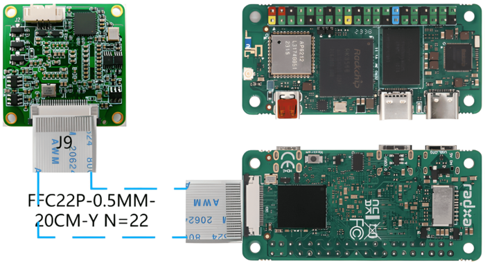
Radxa Zero 3W/3E connect to RAW series camera
3 Introduction to github repositories
https://github.com/veyeimaging/rk35xx_veye_bsp
https://github.com/veyeimaging/rk35xx_radxa
includes:
- driver source code
- i2c toolkits
- application demo
In addition, a compiled linux kernel installation package and Android image is provided in the releases.
4 Upgrade Radxa Debain system
4.1 Overview
This section describes how to update the RK35xx system to support our camera modules.
We provide a deb installation package that can be installed directly.
4.2 Burn Radxa standard system
Refer to the Radxa documentation to burn in a standard system.
The installation package we are currently releasing is based on this image version.
4.3 Using prebuilt Image and dtb file
Using the compiled debain installation package
On the RK35xx board,
Download the latest rk356x_radxa_zero3w.tar.gz or rk356x_radxa_zero3e.tar.gz from https://github.com/veyeimaging/rk35xx_radxa/releases/ .
tar -xavf rk356x_radxa_zero3w.tar.gz
cd rk356x_radxa_zero3w/released_images/mvcam
sudo dpkg -i linux-headers-5.10.160-36-rk356x_5.10.160-36_arm64_mvcam.deb
sudo dpkg -i linux-image-5.10.160-36-rk356x_5.10.160-36_arm64_mvcam.deb
sudo reboot
If the version does not match, it needs to be compiled from the source code.
5 Check system status
5.1 Whether the camera is correctly recognized
After system update, reboot the main board.
Execute the following command on the main board to check if the camera is properly connected.
dmesg | grep mvcam
You can see the camera model and the camera version number probed.
A prompt as below indicates that the MV-MIPI-IMX296M camera is detected on the i2c-2 bus.
mvcam 2-003b: camera is:MV-MIPI-IMX296M
mvcam 2-003b: firmware version: 0x1290133
For Radxa Zero 3W/3E, the camera is connected to i2c-2.
- Check the video0 device node:
ls /dev/video0
You should see:
video0
After successfully identifying the camera, the camera will be recognized as /dev/video0.
6 Camera Application Development Guide
Application Development Guide
7 Compile drivers and dtb from source code
https://github.com/veyeimaging/rk35xx_radxa/tree/main/linux/drivers/rk356x
8 i2c script for parameter configuration
Because of the high degree of freedom of our camera parameters, we do not use V4L2 parameters to control, but use scripts to configure parameters.
https://github.com/veyeimaging/rk35xx_radxa/tree/main/i2c_cmd
using -b option to identify which bus you want to use.
Video Control Toolkits Manual :VEYE-MIPI-327 I2C
9 References
https://docs.radxa.com/zero/zero3
https://radxa-repo.github.io/bsp/
10 Document History
Add a chapter on application development guidelines
Add support for Radxa Zero 3E.
Add description of mv_probe.sh.
Add support for RAW-MIPI-SC535M.
Release 1st version.


