CS-FPD-CAM for Raspberry Pi
1 Introduction
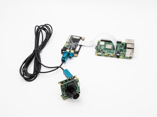
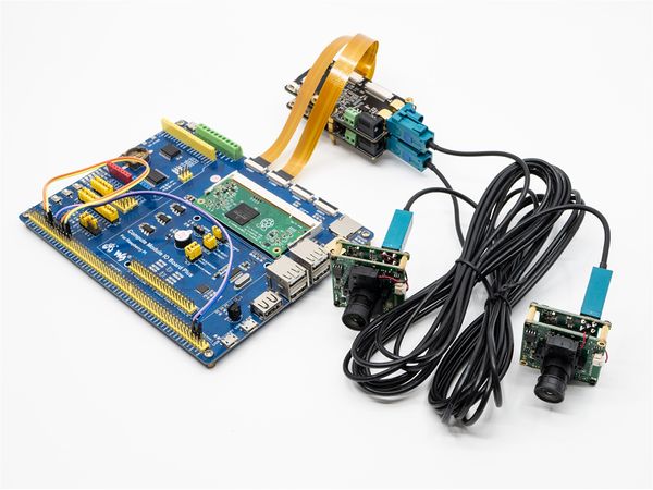
FPD-Link SerDes III is a coaxial remote transmission scheme of video stream provided by TI. We have designed FPD-LINK3-TX and FPD-LINK3-2RX boards, which can realize coaxial transmission of 1 or 2 channels of MIPI CSI-2 images, and the transmission distance can be up to 10 meters.
On the Raspberry PI platform, a set of FPD-LINK3-TX and FPD-LINK3-2RX boards are used to realize the remote transmission of 1-channel video. The I2C address of the camera after initialization configuration is the same as that of the original camera.
For application layer, a completely transparent FPD-Link channel is implemented, including image, i2C communication, synchronous IO and trigger IO.
Therefore, when using CS-FPD-CAM, you must refer to the following articles:
- How to use VEYE-MIPI-X camera module on Raspberry Pi
- How to use CS-MIPI-X camera module on Raspberry Pi
2 Hardware Setup
PS:FPD-LINK3-2RX need a 12V DC power.
3 RaspberryPi System Setup and Configuration
Completely consistent with : RaspberryPi System Setup and Configuration.
4 Sofware Toolkits Install
Completely consistent with : Sofware Toolkits Install.
In addition, we provide a FPD-Link III script for configuring the FPD-Link board.
5 FPD-Link III shell script manual
On Raspberry PI, you need to configure I2C pins, please refer to: raspberry pie pin configuration part2, and then do the following.
5.1 fpdlink3_i2c.sh Usage
$ ./fpdlink3_i2c.sh
Usage: ./fpdlink3_i2c.sh [-f] function name -b bus -p port -p1 param1 -p2 param2 -p3 param3
options:
-f [function name] function name
-b [i2c bus num] i2c bus number
-p [fpdlink port] fpd link port number [0,1]
-p1 [param1] param1 of each function
-p2 [param1] param2 of each function
-p3 [param1] param3 of each function
support functions: rpi_init,sync_init,trigger_init
fpdlink port:FPD-LINK3-2RX board,J3 is fpllink port 0, J4 is fpdlink port 1.
5.2 fpdlink3_i2c.sh usage details
5.2.1 rpi_init
./fpdlink3_i2c.sh -f rpi_init -p 0/1
init the FPD-Link channel of port0/1,must run this command before you can connect video and i2C.
5.2.2 sync_init
./fpdlink3_i2c.sh -f sync_init -p 0 -p1 0
Configure port 0 as the master of sync mode.
Connect J1 signal of FPD-LINK3-TX on port 0 to J6 of FPD-LINK3-2RX,direction is TX-->RX.
./fpdlink3_i2c.sh -f sync_init -p 1 -p1 1
Configure port 1 as the slave of sync mode.
Connect J8 signal of FPD-LINK3-2RX to J1 of FPD-LINK3-TX on port 1 ,direction is RX-->TX.
5.2.3 trigger_init
./fpdlink3_i2c.sh -f trigger_init -p 0
Configure port 0 as the trigger mode.
Connect J6 signal of FPD-LINK3-2RX to J1 of FPD-LINK3-TX on port 0 ,direction is RX-->TX.
./fpdlink3_i2c.sh -f trigger_init -p 1
Configure port 1 as the trigger mode.
Connect J8 signal of FPD-LINK3-2RX to J1 of FPD-LINK3-TX on port 1 ,direction is RX-->TX.
6 Typical application
6.1 CS-FPD-CAM-IMX327 Video usage
6.1.1 Step 1:
On Raspberry PI:
./fpdlink3_i2c.sh -f rpi_init -p 0
Init the FPD-Link channel of port0.
6.1.2 Step 2:
After Step 1, the stream acquisition and I2C instruction control of the camera are exactly the same as those of the camera with the MIPI interface.
- How to use VEYE-MIPI-X camera module on Raspberry Pi
- How to use CS-MIPI-X camera module on Raspberry Pi

