CS-FPD-CAM for Raspberry Pi
1 Introduction
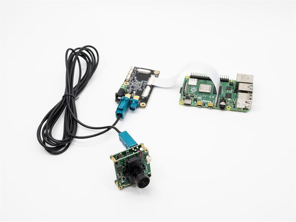
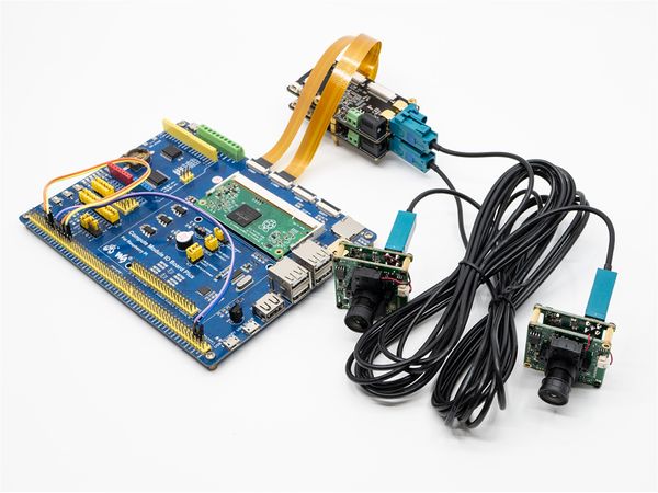
FPD-Link SerDes III is a coaxial remote transmission scheme of video stream provided by TI. We have designed FPD-LINK3-TX and FPD-LINK3-2RX boards, which can realize coaxial transmission of 1 or 2 channels of MIPI CSI-2 images, and the transmission distance can be up to 8meters(RG174 RF Cable) or 10meters(RG58 RF Cable).
On the Raspberry PI platform, a set of FPD-LINK3-TX and FPD-LINK3-2RX boards are used to realize the remote transmission of 1-channel video. The I2C address of the camera after initialization configuration is the same as that of the original camera.
For application layer, a completely transparent FPD-Link channel is implemented, including image, i2C communication, synchronous IO and trigger IO.
Therefore, when using CS-FPD-CAM, you must refer to the following articles:
- How to use VEYE-MIPI-X camera module on Raspberry Pi
- How to use CS-MIPI-X camera module on Raspberry Pi
2 Hardware Setup
PS:FPD-LINK3-2RX need a 12V DC power.
3 RaspberryPi System Setup and Configuration
Completely consistent with : RaspberryPi System Setup and Configuration.
4 Sofware Toolkits Install
Completely consistent with : Sofware Toolkits Install.
In addition, we provide a FPD-Link III script for configuring the FPD-Link board.
5 FPD-Link III shell script manual
On Raspberry PI, you need to configure I2C pins, please refer to: raspberry pie pin configuration part2, and then do the following.
5.1 fpdlink3_i2c.sh Usage
$ ./fpdlink3_i2c.sh
Usage: ./fpdlink3_i2c.sh [-f] function name -b bus -p port -p1 param1 -p2 param2 -p3 param3
options:
-f [function name] function name
-b [i2c bus num] i2c bus number
-p [fpdlink port] fpd link port number [0,1]
-p1 [param1] param1 of each function
-p2 [param1] param2 of each function
-p3 [param1] param3 of each function
support functions: rpi_init,sync_init,trigger_init
fpdlink port:FPD-LINK3-2RX board,J3 is fpllink port 0, J4 is fpdlink port 1.
5.2 fpdlink3_i2c.sh usage details
5.2.1 rpi_init
./fpdlink3_i2c.sh -f rpi_init -p 0/1
init the FPD-Link channel of port0/1,must run this command before you can connect video and i2C.
5.2.2 sync_init
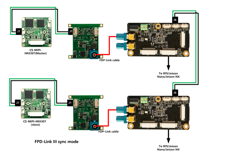
./fpdlink3_i2c.sh -f sync_init -p 0 -p1 0
Configure port 0 as the master of sync mode.
Connect J1 signal of FPD-LINK3-TX on port 0 to J6 of FPD-LINK3-2RX,direction is TX-->RX.
./fpdlink3_i2c.sh -f sync_init -p 1 -p1 1
Configure port 1 as the slave of sync mode.
Connect J8 signal of FPD-LINK3-2RX to J1 of FPD-LINK3-TX on port 1 ,direction is RX-->TX.
5.2.3 trigger_init
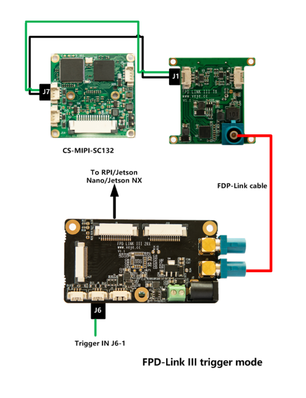
./fpdlink3_i2c.sh -f trigger_init -p 0
Configure port 0 as the trigger mode.
Connect J6 signal of FPD-LINK3-2RX to J1 of FPD-LINK3-TX on port 0 ,direction is RX-->TX.
./fpdlink3_i2c.sh -f trigger_init -p 1
Configure port 1 as the trigger mode.
Connect J8 signal of FPD-LINK3-2RX to J1 of FPD-LINK3-TX on port 1 ,direction is RX-->TX.
6 Typical application
6.1 CS-FPD-CAM Video usage
6.1.1 Step 1:
On Raspberry PI:
./fpdlink3_i2c.sh -f rpi_init -p 0
Init the FPD-Link channel of port0.
6.1.2 Step 2:
After Step 1, the stream acquisition and I2C instruction control of the camera are exactly the same as those of the camera with the MIPI interface.
- How to use VEYE-MIPI-X camera module on Raspberry Pi
- How to use CS-MIPI-X camera module on Raspberry Pi
6.2 CS-FPD-CAM-IMX307 sync mode
6.2.1 Step 1:
On the motherboard of the two cameras, execute:
./fpdlink3_i2c.sh -f rpi_init -p 0 -b [i2c_bus_num]
Init the FPD-Link channel of port0.
6.2.2 Step 2:
After Step 1, the I2C to control camera is ready.
- Configure cam0 as the master
./fpdlink3_i2c.sh -f sync_init -p 0 -p1 0 -b [i2c_bus_num]
./cs_mipi_i2c.sh -w -f streammode -p1 1 -p2 0 -b [i2c_bus_num]
- Configure cam1 as the slave
./fpdlink3_i2c.sh -f sync_init -p 0 -p1 1 -b [i2c_bus_num]
./cs_mipi_i2c.sh -w -f streammode -p1 1 -p2 1 -b [i2c_bus_num]
6.2.3 Step 3:
The stream acquisition and I2C instruction control of the camera are exactly the same as those of the camera with the MIPI interface now.
6.3 CS-FPD-CAM-SC132 Trigger mode
6.3.1 Step 1:
On Raspberry PI:
./fpdlink3_i2c.sh -f rpi_init -p 0
Init the FPD-Link channel of port0.
6.3.2 Step 2:
./fpdlink3_i2c.sh -f trigger_init -p 0
Configure port 0 as trigger mode.
6.3.3 Step 3:
After Step 1, the I2C to control camera is ready.The stream acquisition and I2C instruction control of the camera are exactly the same as those of the camera with the MIPI interface now.
Refer to Camera_module_Trigger_Mode_manual to configure the camera.


