|
|
| (3 intermediate revisions by 2 users not shown) |
| Line 1: |
Line 1: |
| | [https://wiki.veye.cc/index.php/MV_Camera_on_Orange_Pi%27s_RK35XX_Boards/zh 查看中文] | | [https://wiki.veye.cc/index.php/MV_Camera_on_Orange_Pi%27s_RK35XX_Boards/zh 查看中文] |
| | | | |
| − | === Overview === | + | ===Overview=== |
| | The MV series and RAW series cameras are cameras designed for AI applications in the industrial field. They use the MIPI CSI-2 interface and are particularly suitable for use with embedded computing platforms. They have rich data formats and triggering features, extremely low latency, high bandwidth, and reliable stability. | | The MV series and RAW series cameras are cameras designed for AI applications in the industrial field. They use the MIPI CSI-2 interface and are particularly suitable for use with embedded computing platforms. They have rich data formats and triggering features, extremely low latency, high bandwidth, and reliable stability. |
| | | | |
| Line 58: |
Line 58: |
| | |} | | |} |
| | | | |
| − | === Hardware Setup === | + | ===Hardware Setup=== |
| | We use the official baseboards of the Orange Pi CM4 and CM5, which feature a 15-pin header compatible with Raspberry Pi. For the RAW series cameras, our cameras can be directly mounted onto the baseboard without the need for an adapter board. For the MV series cameras, the ADP-MV1 adapter board is required for connection. | | We use the official baseboards of the Orange Pi CM4 and CM5, which feature a 15-pin header compatible with Raspberry Pi. For the RAW series cameras, our cameras can be directly mounted onto the baseboard without the need for an adapter board. For the MV series cameras, the ADP-MV1 adapter board is required for connection. |
| | | | |
| − | ==== Camera Connection to Orange Pi CM4 ==== | + | ====Camera Connection to Orange Pi CM4==== |
| | The ADP-MV1 is connected to the OrangePi CM4 via a 15-pin FFC cable with opposite surface alignment; please pay attention to the orientation of the contact surfaces. | | The ADP-MV1 is connected to the OrangePi CM4 via a 15-pin FFC cable with opposite surface alignment; please pay attention to the orientation of the contact surfaces. |
| | | | |
| Line 68: |
Line 68: |
| | The OrangePi CM5 supports up to four cameras. The following diagram shows the hardware connection method for simultaneously connecting multiple cameras.[[File:OrangePi CM5 to all cam overview.jpg|center|thumb|600x600px|OrangePi CM5 to all cam overview|link=http://wiki.veye.cc/index.php/File:OrangePi_CM5_to_all_cam_overview.jpg]][[File:OrangePi CM5 to all cam backview.jpg|center|thumb|600x600px|OrangePi CM5 to all cam backview|link=http://wiki.veye.cc/index.php/File:OrangePi_CM5_to_all_cam_backview.jpg]]<br /> | | The OrangePi CM5 supports up to four cameras. The following diagram shows the hardware connection method for simultaneously connecting multiple cameras.[[File:OrangePi CM5 to all cam overview.jpg|center|thumb|600x600px|OrangePi CM5 to all cam overview|link=http://wiki.veye.cc/index.php/File:OrangePi_CM5_to_all_cam_overview.jpg]][[File:OrangePi CM5 to all cam backview.jpg|center|thumb|600x600px|OrangePi CM5 to all cam backview|link=http://wiki.veye.cc/index.php/File:OrangePi_CM5_to_all_cam_backview.jpg]]<br /> |
| | | | |
| − | ==== Camera Connection to Orange Pi CM5 tablet ==== | + | ====Camera Connection to Orange Pi CM5 tablet==== |
| | Due to differences in connector formats, we have successfully interfaced modules for both CAM2 and CAM3 on the OrangePi CM5 tablet. The diagram below illustrates the connection methods for the RAW series and MV series. | | Due to differences in connector formats, we have successfully interfaced modules for both CAM2 and CAM3 on the OrangePi CM5 tablet. The diagram below illustrates the connection methods for the RAW series and MV series. |
| | <br /> | | <br /> |
| Line 111: |
Line 111: |
| | <code>video0</code> | | <code>video0</code> |
| | | | |
| − | ==== CM5 ==== | + | ====CM5==== |
| | The CM5 supports the connection of up to four cameras. Taking the RAW-MIPI-SC132M as an example, the <code>dmesg</code> output contains the following information: | | The CM5 supports the connection of up to four cameras. Taking the RAW-MIPI-SC132M as an example, the <code>dmesg</code> output contains the following information: |
| | | | |
| Line 129: |
Line 129: |
| | | | |
| | <code>mvcam 6-003b: firmware version: 0x1040000</code> | | <code>mvcam 6-003b: firmware version: 0x1040000</code> |
| − | ===='''State Detection and Environment Variable Configuration'''==== | + | ====CM5 tablet==== |
| − | [https://github.com/veyeimaging/rk35xx_veye_bsp/tree/main/mv_tools_rockchip/i2c_tools Here], we provide an <code>mv_probe.sh</code> script that automatically detects the connected camera and configures environment variables with its default model, width, height, frame rate, and other information.
| + | The CM5 supports the connection of up to two cameras. Taking the RAW-MIPI-SC132M as an example, the <code>dmesg</code> output contains the following information: |
| | | | |
| − | Usage:
| + | <code>mvcam 6-003b: camera is: RAW-MIPI-SC132M</code> |
| | | | |
| − | <code>source ./mv_probe.sh</code> | + | <code>mvcam 6-003b: firmware version: 0x1040000</code> |
| | | | |
| − | A typical output:
| + | <code>mvcam 7-003b: camera is: RAW-MIPI-SC132M</code> |
| | | | |
| − | <code>$ source ./mv_probe.sh</code> | + | <code>mvcam 7-003b: firmware version: 0x1040000</code> |
| | | | |
| − | <code>The mvcam driver is loaded on i2c-10, but the camera is not detected!</code>
| + | ===Camera Application Development Guide=== |
| | + | [[MV Camera Application Development Guide on Rochchip|Application Development Guide]] |
| | | | |
| − | <code>Found veye_mvcam camera on i2c-11.</code>
| + | ===References=== |
| − | | |
| − | <code>Setenv CAMERAMODEL = RAW-MIPI-SC535M</code>
| |
| − | | |
| − | <code>Setenv FPS = 49</code>
| |
| − | | |
| − | <code>Setenv HEIGHT = 2048</code>
| |
| − | | |
| − | <code>Setenv WIDTH = 2432</code>
| |
| − | | |
| − | You can verify the environment variable output using:
| |
| − | | |
| − | <code>echo $CAMERAMODEL</code>
| |
| − | | |
| − | Note that these environment variables are only valid for the current session.
| |
| − | | |
| − | '''Important Notes:'''
| |
| − | | |
| − | * This script requires the <code>mvcam</code> driver version '''1.1.06 or later'''.
| |
| − | *If your driver version is '''earlier than 1.1.06''' or you need to use different width, height, or frame rate values, refer to the camera module manual and manually configure the following environment variables. Otherwise, subsequent programs may not function correctly.
| |
| − | | |
| − | Example:
| |
| − | | |
| − | <code>export WIDTH=2432</code>
| |
| − | | |
| − | <code>export HEIGHT=2048</code>
| |
| − | | |
| − | <code>export FPS=50</code>
| |
| − | ==== Configuring Global Variables ====
| |
| − | Set the <code>I2C_BUS</code> global variable based on the board model. Below are examples for two different boards, each with one camera as an example.
| |
| | | | |
| | *OrangePi CM4 | | *OrangePi CM4 |
| | | | |
| − | <code>export I2C_BUS=1</code>
| + | http://www.orangepi.cn/orangepiwiki/index.php/Orange_Pi_CM4 |
| | | | |
| | *OrangePi CM5 | | *OrangePi CM5 |
| | | | |
| − | <code>export I2C_BUS=6</code>
| + | http://www.orangepi.cn/html/hardWare/computerAndMicrocontrollers/service-and-support/Orange-Pi-CM5.html |
| − | | + | ===Document History=== |
| − | ==== Viewing the Topology with <code>media-ctl</code> ==== | |
| − | Let's take CM5's CAM1 as an example for explanation.
| |
| − | | |
| − | By using the <code>media-ctl</code> command, you can clearly display the current topology.
| |
| − | | |
| − | <code>media-ctl -p -d /dev/media2</code>
| |
| | | | |
| − | =====Link relationship=====
| + | *2025-12-26 |
| − | mv camera->rockchip-csi2-dphy1->rockchip-mipi-csi2->stream_cif_mipi_id0 - - ->DDR(/dev/video22)
| |
| | | | |
| − | The application can obtain images through the <code>/dev/video22</code> node.
| + | Add a chapter on application development guidelines |
| | | | |
| − | ===== mv camera entity information =====
| + | *2025-09-16 |
| − | Taking the RAW-MIPI-SC132M as an example:
| |
| | | | |
| − | <code>- entity 63: m00_b_mvcam 4-003b (1 pad, 1 link)</code>
| + | Add support for CM5 tablet. |
| − | | |
| − | <code> type V4L2 subdev subtype Sensor flags 0</code>
| |
| − | | |
| − | <code> device node name /dev/v4l-subdev8</code>
| |
| − | | |
| − | <code> pad0: Source</code>
| |
| − | | |
| − | <code> [fmt:Y8_1X8/1080x1280@100/12000 field:none]</code>
| |
| − | | |
| − | <code> -> "rockchip-csi2-dphy1":0 [ENABLED]</code>
| |
| − | | |
| − | You can see that:
| |
| − | | |
| − | *The complete name of this entity is: <code>m00_b_mvcam 4-003b</code>.
| |
| − | *It is a V4L2 subdev (Sub-Device) Sensor.
| |
| − | *Its corresponding node is <code>/dev/v4l-subdev8</code>, which can be opened and configured by applications (such as <code>v4l2-ctl</code>).
| |
| − | *Its output format is <code>[fmt:Y8_1X8/1080x1280@100/12000 field:none]</code>, where <code>Y8_1X8</code> is a shorthand for a mbus-code, which will be listed in the next section of this article.
| |
| − | *The current resolution is <code>1080x1280</code>.
| |
| − | *The current frame interval is <code>100/12000</code>, which means the frame rate is 120.
| |
| − | *The data format output by the camera can be modified using the media-ctl command.
| |
| − | | |
| − | The correspondence of the various information is as follows:
| |
| − | | |
| − | - CM4
| |
| − | {| class="wikitable"
| |
| − | !CAM num
| |
| − | !I2C
| |
| − | !media node
| |
| − | !media entity name
| |
| − | !video node
| |
| − | !subdev node
| |
| − | |-
| |
| − | |1
| |
| − | |1
| |
| − | |/dev/media0
| |
| − | |m00_b_mvcam 1-003b
| |
| − | |/dev/video0
| |
| − | |/dev/v4l-subdev2
| |
| − | |}- CM5
| |
| − | {| class="wikitable"
| |
| − | !CAM num
| |
| − | !I2C
| |
| − | !media node
| |
| − | !media entity name
| |
| − | !video node
| |
| − | !subdev node
| |
| − | |-
| |
| − | |1
| |
| − | |4
| |
| − | |/dev/media2
| |
| − | |m00_b_mvcam 4-003b
| |
| − | |/dev/video22
| |
| − | |/dev/v4l-subdev8
| |
| − | |-
| |
| − | |2
| |
| − | |3
| |
| − | |/dev/media3
| |
| − | |m01_b_mvcam 3-003b
| |
| − | |/dev/video33
| |
| − | |/dev/v4l-subdev11
| |
| − | |-
| |
| − | |3
| |
| − | |5
| |
| − | |/dev/media1
| |
| − | |m00_b_mvcam 5-003b
| |
| − | |/dev/video11
| |
| − | |/dev/v4l-subdev5
| |
| − | |-
| |
| − | |4
| |
| − | |6
| |
| − | |/dev/media0
| |
| − | |m00_b_mvcam 6-003b
| |
| − | |/dev/video0
| |
| − | |/dev/v4l-subdev2
| |
| − | |}
| |
| − | =====mbus-code list=====
| |
| − | MV series and RAW series cameras have different data format capabilities, which can be found in the data manual for each camera model.
| |
| − | {| class="wikitable"
| |
| − | !Format on datasheet
| |
| − | !mbus-code for media-ctl
| |
| − | !FourCC pixelformat for v4l2-ctl
| |
| − | |-
| |
| − | |RAW8
| |
| − | |Y8_1X8
| |
| − | |GREY
| |
| − | |-
| |
| − | |RAW10
| |
| − | |Y10_1X10
| |
| − | |'Y10 '
| |
| − | |-
| |
| − | |RAW12
| |
| − | |Y12_1X12
| |
| − | |'Y12 '
| |
| − | |-
| |
| − | |UYVY
| |
| − | |UYVY8_2X8
| |
| − | |UYVY
| |
| − | |}
| |
| − | ===Raw data format===
| |
| − | The VICAP module of RK3588 supports two data saving formats, Compact and Noncompact RAW. You can modify the mode using the RKCIF_CMD_SET_CSI_MEMORY_MODE ioctl command of RKCIF. By default, the output is in Compact RAW format.[[File:Compact raw and noncompact raw of rk3588 vicap.png|center|thumb|800x800px|Compact raw and noncompact raw of rk3588 VICAP|link=http://wiki.veye.cc/index.php/File:Compact_raw_and_noncompact_raw_of_rk3588_vicap.png]]
| |
| − | ====Noncompact RAW====
| |
| − | For pixel data with 10-bit depth or 12-bit depth, two bytes are always used to store one pixel. This storage method is convenient for software processing, but it has the disadvantage of occupying a large amount of space.
| |
| − | | |
| − | Depending on whether the effective data is stored in the high bits or low bits, it can be further divided into two types: high align and low align.
| |
| − | =====Noncompact RAW(high align)=====
| |
| − | Data is saved to the high bits, and the unused low bits are filled with 0. This is one of the data formats supported by RK VICAP.
| |
| − | =====Noncompact RAW(low align)=====
| |
| − | In Noncompact RAW (low align) format, data is saved to the low bits, and the unused high bits are filled with 0. The V4L2 standard 'Y10' (10-bit Greyscale) and 'Y12' (12-bit Greyscale) formats are both stored in this way.
| |
| − | | |
| − | The pixel_layer_convert conversion tool mentioned later in the article also converts Compact RAW to this storage format for easy display using image players.
| |
| − | ====Compact RAW====
| |
| − | As shown above,there is no bit padding between pixels in this storage format.
| |
| − | ====Line stride====
| |
| − | To facilitate fast operations on images, the system usually provides row-aligned buffer sizes for each line of data. RK3588 uses 256-byte alignment for this purpose.
| |
| − | | |
| − | line_stride = ALIGN_UP(image_width*bits_per_pixel/8,256)
| |
| − | | |
| − | For example, when the image width is 1456:
| |
| − | | |
| − | 8bit depth,line_stride=1536
| |
| − | | |
| − | 10bit depth,preferred_stride=2048
| |
| − | | |
| − | 12bit depth,preferred_stride=2304
| |
| − | ====Format convert tool====
| |
| − | We have written a small tool: [https://github.com/veyeimaging/pixel_layer_convert pixel_layer_convert], which can easily convert Compact images to Noncompact (low align) images.
| |
| − | | |
| − | For example, the following command can convert a Compact RAW10 image with a width of 1456 to Noncompact RAW10 format:
| |
| − | | |
| − | <code>./pixel_layer_convert -I R10C -i y10-1456x1088_0001.raw -o y10-1456x1088_0001_new.raw -w 1456</code>
| |
| − | ====Raw data image player====
| |
| − | We recommend using [https://www.offminor.de/ vooya] as the player, which supports GREY, and unpacked image formats.
| |
| − | | |
| − | Also, y8 file can be used with this player: [https://yuv-player-deluxe.software.informer.com/2.6/ YUV Displayer Deluxe].
| |
| − | | |
| − | === Application Example ===
| |
| − | Please note that in the following sections, <code>/dev/media0</code>, <code>/dev/video0</code>, and <code>/dev/v4l-subdev2</code> should be replaced with the actual values as described in the previous sections.
| |
| − | ====Configure parameters using v4l2-ctl====
| |
| − | <code>$ v4l2-ctl -d /dev/v4l-subdev2 -L</code>
| |
| − | | |
| − | <code>User Controls</code>
| |
| − | | |
| − | <code> trigger_mode 0x00981901 (int) : min=0 max=2 step=1 default=0 value=0 flags=volatile, execute-on-write</code>
| |
| − | | |
| − | <code> trigger_src 0x00981902 (int) : min=0 max=1 step=1 default=1 value=1 flags=volatile, execute-on-write</code>
| |
| − | | |
| − | <code> soft_trgone 0x00981903 (button) : flags=write-only, execute-on-write</code>
| |
| − | | |
| − | <code> frame_rate 0x00981904 (int) : min=1 max=60 step=1 default=60 value=60 flags=volatile, execute-on-write</code>
| |
| − | | |
| − | <code> roi_x 0x00981905 (int) : min=0 max=1376 step=8 default=0 value=0</code>
| |
| − | | |
| − | <code> roi_y 0x00981906 (int) : min=0 max=1024 step=4 default=0 value=0</code>
| |
| − | | |
| − | Parameters can be set and get using the following methods.
| |
| − | | |
| − | <code>v4l2-ctl --set-ctrl [ctrl_type]=[val]</code>
| |
| − | | |
| − | <code>v4l2-ctl --get-ctrl [ctrl_type]</code>
| |
| − | | |
| − | All the above functions can be implemented using [[Mv mipi i2c.sh user guide|mv_mipi_i2c.sh]].
| |
| − | | |
| − | Note that the above parameters cannot be modified during the capture process.
| |
| − | | |
| − | The following is an explanation of each parameter:
| |
| − | =====Trigger Mode=====
| |
| − | <code>v4l2-ctl --set-ctrl <small>trigger_mode=[0-2]</small></code>
| |
| − | | |
| − | 0:Video streaming mode
| |
| − | | |
| − | 1:Normal trigger mode.
| |
| − | | |
| − | 2:High-speed continuous trigger mode.
| |
| − | =====Trigger Source=====
| |
| − | <code>v4l2-ctl --set-ctrl <small>trigger_src=[0-1]</small></code>
| |
| − | | |
| − | 0: Software trigger mode.
| |
| − | | |
| − | 1: Hardware trigger mode.
| |
| − | =====Software trigger command=====
| |
| − | <code>v4l2-ctl --set-ctrl <small>soft_trgone=1</small></code>
| |
| − | =====Set frame rate=====
| |
| − | <code>v4l2-ctl --set-ctrl frame_rate=[1-max]</code>
| |
| − | | |
| − | The maximum frame rate is automatically updated as the resolution changed.
| |
| − | =====Set the starting position of the ROI=====
| |
| − | <code>v4l2-ctl -d /dev/v4l-subdev2 --set-ctrl roi_x=0</code>
| |
| − | | |
| − | <code>v4l2-ctl -d /dev/v4l-subdev2 --set-ctrl roi_y=0</code>
| |
| − | | |
| − | After setting the ROI starting position, you need to complete the full ROI configuration using the <code>media-ctl</code> command.
| |
| − | | |
| − | Note that setting the ROI may affect the maximum frame rate, and the ROI parameters need to meet the requirements specified in the camera manual.
| |
| − | ====Set image format using media-ctl====
| |
| − | use the following command to configure the camera's data format, resolution, and frame rate using <code>media-ctl</code>:
| |
| − | | |
| − | <code>media-ctl -d /dev/media0 --set-v4l2 '"m00_b_mvcam '"$I2C_BUS"'-003b":0[fmt:Y8_1X8/'"$WIDTH"'x'"$HEIGHT"'@1/'"$FPS"']'</code>
| |
| − | | |
| − | Among them: <code>"m00_b_mvcam '"$I2C_BUS"'-003b"</code> refers to the complete name of the camera entity, <code>Y8_1X8</code> is the mbus-code, <code>'"$WIDTH"'x'"$HEIGHT"'</code> indicates the resolution, <code>1/'"$FPS"'</code> indicates the resolution frame rate.
| |
| − | | |
| − | The width and height here cooperate with the roi_x and roi_y of the v4l2-ctl command to form the ROI parameter.
| |
| − | | |
| − | For example, for MV-MIPI-IMX296M, the command after variable replacement would be:
| |
| − | | |
| − | <code>media-ctl -d /dev/media0 --set-v4l2 '"m00_b_mvcam 6-003b":0[fmt:Y8_1X8/1456x1088@1/60 field:none]'</code>
| |
| − | | |
| − | You can not only configure the data format, resolution, and frame rate in one command, but also modify them separately as needed.
| |
| − | ====Video Streaming mode====
| |
| − | =====Set data format, resolution, frame rate=====
| |
| − | <code>v4l2-ctl -d /dev/v4l-subdev2 --set-ctrl roi_x=0</code>
| |
| − | | |
| − | <code>v4l2-ctl -d /dev/v4l-subdev2 --set-ctrl roi_y=0</code>
| |
| − | | |
| − | <code>media-ctl -d /dev/media0 --set-v4l2 '"m00_b_mvcam '"$I2C_BUS"'-003b":0[fmt:Y8_1X8/'"$WIDTH"'x'"$HEIGHT"'@1/'"$FPS"']'</code>
| |
| − | =====Frame rate statistics=====
| |
| − | In streaming mode, the following commands can be used for frame rate statistics:
| |
| − | | |
| − | <code>v4l2-ctl --set-fmt-video=width=$WIDTH,height=$HEIGHT,pixelformat=GREY --stream-mmap --stream-count=-1 --stream-to=/dev/null</code>
| |
| − | | |
| − | Or:
| |
| − | | |
| − | <code>./yavta -c1000 --skip 0 -f Y8 -s ${WIDTH}x${HEIGHT} /dev/video0</code>
| |
| − | =====Save image to file=====
| |
| − | | |
| − | *raw8
| |
| − | | |
| − | <code>v4l2-ctl -d /dev/video0 --set-fmt-video=width=$WIDTH,height=$HEIGHT,pixelformat=GREY --stream-mmap --stream-count=1 --stream-to=y8-${WIDTH}x${HEIGHT}.raw</code>
| |
| − | | |
| − | *raw10
| |
| − | | |
| − | <code>v4l2-ctl -d /dev/video0 --set-fmt-video=width=$WIDTH,height=$HEIGHT,pixelformat='Y10 ' --stream-mmap --stream-count=1 --stream-to=y10-${WIDTH}x${HEIGHT}.raw</code>
| |
| − | | |
| − | *raw12
| |
| − | | |
| − | <code>v4l2-ctl -d /dev/video0 --set-fmt-video=width=$WIDTH,height=$HEIGHT,pixelformat='Y12 ' --stream-mmap --stream-count=1 --stream-to=y12-${WIDTH}x${HEIGHT}.raw</code>
| |
| − | | |
| − | Please refer to the description in the previous section for the image format.
| |
| − | =====Example of yavta=====
| |
| − | ======Install yavta======
| |
| − | <code>git clone <nowiki>git://git.ideasonboard.org/yavta.git</nowiki></code>
| |
| − | | |
| − | <code>cd yavta;make</code>
| |
| − | ======Save image to file======
| |
| − | After setting data format, resolution, frame rate,run:
| |
| − | | |
| − | <code>./yavta -c1 -Fy8-${WIDTH}x${HEIGHT}.raw --skip 0 -f Y8 -s ${WIDTH}x${HEIGHT} /dev/video0</code>
| |
| − | =====Example of import image to OpenCV=====
| |
| − | <code>sudo apt install python3-opencv</code>
| |
| − | | |
| − | See the [https://github.com/veyeimaging/rk356x_firefly/tree/main/linux/samples samples] directory on github for details.
| |
| − | | |
| − | <code>python ./v4l2dev_2_opencv_show_grey.py --width 1456 --height 1088 --fps 60 --i2c 7</code>
| |
| − | =====Example of gstreamer application=====
| |
| − | We provide several gstreamer routines that implement the preview function. See the [https://github.com/veyeimaging/rk35xx_veye_bsp/tree/main/samples samples] directory on github for details.
| |
| − | ====Trigger mode====
| |
| − | =====Set data format, resolution, frame rate=====
| |
| − | <code>v4l2-ctl -d /dev/v4l-subdev2 --set-ctrl roi_x=0</code>
| |
| − | | |
| − | <code>v4l2-ctl -d /dev/v4l-subdev2 --set-ctrl roi_y=0</code>
| |
| − | | |
| − | <code>media-ctl -d /dev/media0 --set-v4l2 '"m00_b_mvcam '"$I2C_BUS"'-003b":0[fmt:Y8_1X8/'"$WIDTH"'x'"$HEIGHT"'@1/'"$FPS"']'</code>
| |
| − | =====Software trigger mode=====
| |
| − | ======Set mode======
| |
| − | <code>v4l2-ctl -d /dev/v4l-subdev2 --set-ctrl <small>trigger_mode=1</small></code>
| |
| − | | |
| − | <code>v4l2-ctl -d /dev/v4l-subdev2 --set-ctrl <small>trigger_src=0</small></code>
| |
| − | ======Start acquisition======
| |
| − | <code>v4l2-ctl -d /dev/video0 --set-fmt-video=width=$WIDTH,height=$HEIGHT,pixelformat=GREY --stream-mmap --stream-count=1 --stream-to=y8-${WIDTH}x${HEIGHT}.raw</code>
| |
| − | ======Perform soft trigger operation======
| |
| − | In other shell terminals, you can execute the following command multiple times for multiple triggers.
| |
| − | | |
| − | <code>v4l2-ctl -d /dev/v4l-subdev2 --set-ctrl <small>soft_trgone=1</small></code>
| |
| − | =====Hardware trigger mode=====
| |
| − | ======Set mode======
| |
| − | <code>v4l2-ctl -d /dev/v4l-subdev2 --set-ctrl <small>trigger_mode=1</small></code>
| |
| − | | |
| − | <code>v4l2-ctl -d /dev/v4l-subdev2 --set-ctrl <small>trigger_src=1</small></code>
| |
| − | | |
| − | The [[Mv mipi i2c.sh user guide|mv_mipi_i2c.sh]] script can be used to set rich trigger parameters.
| |
| − | ======Start acquisition======
| |
| − | <code>v4l2-ctl -d /dev/video0 --set-fmt-video=width=$WIDTH,height=$HEIGHT,pixelformat=GREY --stream-mmap --stream-count=1 --stream-to=y8-${WIDTH}x${HEIGHT}.raw</code>
| |
| − | ======Perform hardware trigger operation======
| |
| − | Connect the appropriate trigger signal to the trigger pin of the camera and trigger it.
| |
| − | ===i2c script for parameter configuration===
| |
| − | We provide shell scripts to configure the parameters.
| |
| − | | |
| − | [[mv_mipi_i2c.sh user guide]]
| |
| − | ===References===
| |
| − | | |
| − | *OrangePi CM4
| |
| − | | |
| − | http://www.orangepi.cn/orangepiwiki/index.php/Orange_Pi_CM4
| |
| − | | |
| − | *OrangePi CM5
| |
| − | | |
| − | http://www.orangepi.cn/html/hardWare/computerAndMicrocontrollers/service-and-support/Orange-Pi-CM5.html
| |
| − | ===Document History===
| |
| | | | |
| − | * 2025-03-23 | + | *2025-03-23 |
| | | | |
| | Add description of mv_probe.sh. | | Add description of mv_probe.sh. |
查看中文
1 Overview
The MV series and RAW series cameras are cameras designed for AI applications in the industrial field. They use the MIPI CSI-2 interface and are particularly suitable for use with embedded computing platforms. They have rich data formats and triggering features, extremely low latency, high bandwidth, and reliable stability.
This article takes OrangePi CM4 and OrangePi CM5 and CM5 tablet board as an example to introduce how to connect MV and RAW series cameras to the RK3566/3K3568 and RK3588S/RK3588 system.
We provide drivers for the Linux operating system (using Ubuntu as an example).
1.1 Camera Module List
| Series
|
Model
|
Status
|
| MV series
|
MV-MIPI-IMX178M
|
Done
|
| MV series
|
MV-MIPI-SC130M
|
Done
|
| MV series
|
MV-MIPI-IMX296M
|
Done
|
| MV series
|
MV-MIPI-IMX287M
|
Done
|
| MV series
|
MV-MIPI-IMX265M
|
Done
|
| MV series
|
MV-MIPI-IMX264M
|
Done
|
| MV series
|
MV-MIPI-GMAX4002M
|
Done
|
| RAW series
|
RAW-MIPI-SC132M
|
Done
|
| RAW series
|
RAW-MIPI-IMX462M
|
Done
|
| RAW series
|
RAW-MIPI-AR0234M
|
Done
|
| RAW series
|
RAW-MIPI-SC535M
|
Done
|
2 Hardware Setup
We use the official baseboards of the Orange Pi CM4 and CM5, which feature a 15-pin header compatible with Raspberry Pi. For the RAW series cameras, our cameras can be directly mounted onto the baseboard without the need for an adapter board. For the MV series cameras, the ADP-MV1 adapter board is required for connection.
2.1 Camera Connection to Orange Pi CM4
The ADP-MV1 is connected to the OrangePi CM4 via a 15-pin FFC cable with opposite surface alignment; please pay attention to the orientation of the contact surfaces.
Note that only the CAM1 shown in the image below supports MV and RAW cameras.
2.2 Camera Connection to Orange Pi CM5
The OrangePi CM5 supports up to four cameras. The following diagram shows the hardware connection method for simultaneously connecting multiple cameras.

OrangePi CM5 to all cam overview
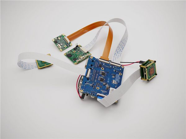
OrangePi CM5 to all cam backview
2.3 Camera Connection to Orange Pi CM5 tablet
Due to differences in connector formats, we have successfully interfaced modules for both CAM2 and CAM3 on the OrangePi CM5 tablet. The diagram below illustrates the connection methods for the RAW series and MV series.
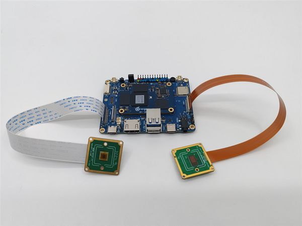
OrangePi CM5 tablet to RAW cam
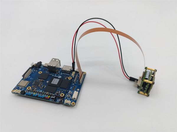
OrangePi CM5 tablet to MV cam
3 Introduction to github repositories
https://github.com/veyeimaging/rk35xx_veye_bsp
https://github.com/veyeimaging/rk35xx_orangepi
includes:
- driver source code
- i2c toolkits
- application demo
In addition, a compiled linux kernel installation package is provided in the releases.
4 Upgrade the Ubuntu system
We provide a flashing image for the release system, as well as a deb package for the Linux kernel.
Refer to the OrangePi CM4 user manual or the OrangePi CM5 user manual for instructions on flashing the system. Alternatively, you can use the general dpkg command to install the deb package.
5 Check system status
Run the following command to confirm whether the camera is probed.
sudo dmesg | grep mvcam
5.1 CM4
The CM4 supports camera connection only through the CAM1 interface. Taking the RAW-MIPI-SC132M as an example, the dmesg output contains the following information:
The output message appears as shown below:
mvcam 1-003b: camera is: RAW-MIPI-SC132M
mvcam 1-003b: firmware version: 0x1040000
- Run the following command to check the presence of video node.
ls /dev/video0
The output message appears as shown below.
video0
5.2 CM5
The CM5 supports the connection of up to four cameras. Taking the RAW-MIPI-SC132M as an example, the dmesg output contains the following information:
mvcam 3-003b: camera is: RAW-MIPI-SC132M
mvcam 3-003b: firmware version: 0x1040000
mvcam 4-003b: camera is: RAW-MIPI-SC132M
mvcam 4-003b: firmware version: 0x1040000
mvcam 5-003b: camera is: RAW-MIPI-SC132M
mvcam 5-003b: firmware version: 0x1040000
mvcam 6-003b: camera is: RAW-MIPI-SC132M
mvcam 6-003b: firmware version: 0x1040000
5.3 CM5 tablet
The CM5 supports the connection of up to two cameras. Taking the RAW-MIPI-SC132M as an example, the dmesg output contains the following information:
mvcam 6-003b: camera is: RAW-MIPI-SC132M
mvcam 6-003b: firmware version: 0x1040000
mvcam 7-003b: camera is: RAW-MIPI-SC132M
mvcam 7-003b: firmware version: 0x1040000
6 Camera Application Development Guide
Application Development Guide
7 References
http://www.orangepi.cn/orangepiwiki/index.php/Orange_Pi_CM4
http://www.orangepi.cn/html/hardWare/computerAndMicrocontrollers/service-and-support/Orange-Pi-CM5.html
8 Document History
Add a chapter on application development guidelines
Add support for CM5 tablet.
Add description of mv_probe.sh.
Release 1st version.


