Difference between revisions of "MV Camera on Orange Pi's RK35XX Boards"

From wiki_veye
Jump to navigation Jump to search
 
(2 intermediate revisions by the same user not shown)
Line 1: Line 1:
 
[https://wiki.veye.cc/index.php/MV_Camera_on_Orange_Pi%27s_RK35XX_Boards/zh 查看中文]
 
[https://wiki.veye.cc/index.php/MV_Camera_on_Orange_Pi%27s_RK35XX_Boards/zh 查看中文]
  
'''<big>怎样在Orange Pi的RK35XX板子上使用MV系列和RAW系列相机</big>'''
+
=== Overview ===
===概述 ===
+
The MV series and RAW series cameras are cameras designed for AI applications in the industrial field. They use the MIPI CSI-2 interface and are particularly suitable for use with embedded computing platforms. They have rich data formats and triggering features, extremely low latency, high bandwidth, and reliable stability.
MV系列和RAW系列相机是为工业领域的AI应用推出的相机。其使用MIPI CSI-2接口,尤其适合嵌入式运算平台使用。它具备丰富的数据格式和触发特性,极低的延时,极高的带宽和可靠的稳定性。
 
  
本文以Orange Pi的CM4和CM5主板为例,介绍怎样将MV和RAW系列摄像机接入RK3566/3K3568系统。
+
This article takes OrangePi CM4 and OrangePi CM5 board as an example to introduce how to connect MV and RAW series cameras to the RK3566/3K3568 and RK3588S/RK3588 system.
  
我们提供了Linux操作系统下的驱动。
+
We provide drivers for the Linux operating system (using Ubuntu as an example).
====支持的模组====
+
====Camera Module List====
 
{| class="wikitable"
 
{| class="wikitable"
!系列
+
!Series
!型号
+
!Model
!状态
+
!Status
 
|-
 
|-
|MV系列
+
|MV series
 
|MV-MIPI-IMX178M
 
|MV-MIPI-IMX178M
|完成
+
|Done
 
|-
 
|-
|MV系列
+
|MV series
 
|MV-MIPI-SC130M
 
|MV-MIPI-SC130M
|完成
+
|Done
 
|-
 
|-
|MV系列
+
|MV series
 +
|MV-MIPI-IMX296M
 +
|Done
 +
|-
 +
|MV series
 
|MV-MIPI-IMX287M
 
|MV-MIPI-IMX287M
|完成
+
|Done
|-
 
|MV系列
 
|MV-MIPI-IMX296M
 
|完成
 
 
|-
 
|-
|MV系列
+
|MV series
 
|MV-MIPI-IMX265M
 
|MV-MIPI-IMX265M
|完成
+
|Done
 
|-
 
|-
|MV系列
+
|MV series
 
|MV-MIPI-IMX264M
 
|MV-MIPI-IMX264M
|完成
+
|Done
 
|-
 
|-
|RAW系列
+
|RAW series
 
|RAW-MIPI-SC132M
 
|RAW-MIPI-SC132M
|完成
+
|Done
 
|-
 
|-
|RAW系列
+
|RAW series
 
|RAW-MIPI-IMX462M
 
|RAW-MIPI-IMX462M
|完成
+
|Done
 
|-
 
|-
|RAW系列
+
|RAW series
 
|RAW-MIPI-AR0234M
 
|RAW-MIPI-AR0234M
|完成
+
|Done
 
|-
 
|-
|RAW系列
+
|RAW series
 
|RAW-MIPI-SC535M
 
|RAW-MIPI-SC535M
|完成
+
|Done
 
|}
 
|}
===硬件准备及安装===
 
我们使用Orange Pi的CM4和CM5的官方底板,这两个底板提供了兼容树莓派的15Pin端子。对于RAW系列相机,无需使用转接板即可将我们的相机安装到其主板上。对于MV系列相机,则需要使用[[ADP-MV1 Adapter Board Data Sheet/zh|ADP-MV1]]转接板进行连接。
 
  
==== 相机与OrangePi CM4的连接 ====
+
=== Hardware Setup ===
ADP-MV1和Zero 3W之间使用15P的FFC异面线连接,注意接触面方向。
+
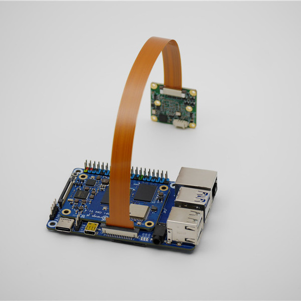
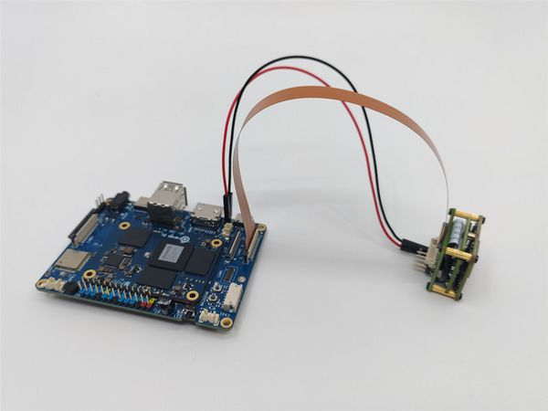
We use the official baseboards of the Orange Pi CM4 and CM5, which feature a 15-pin header compatible with Raspberry Pi. For the RAW series cameras, our cameras can be directly mounted onto the baseboard without the need for an adapter board. For the MV series cameras, the ADP-MV1 adapter board is required for connection.
[[File:OrangePi CM4 to MV cam.jpg|center|thumb|600x600px|OrangePi CM4 to MV cam]]
 
[[File:OrangePi CM4 to RAW cam.jpg|center|thumb|600x600px|OrangePi CM4 to RAW cam]]
 
<br />
 
  
==== 相机与OrangePi CM5的连接 ====
+
==== Camera Connection to Orange Pi CM4 ====
OrangePi CM5最多支持4个VEYE摄像头,下图是同时连接多种摄像头的硬件连接方法展示。[[File:OrangePi CM5 to all cam overview.jpg|center|thumb|600x600px|OrangePi CM5 to all cam overview|link=http://wiki.veye.cc/index.php/File:OrangePi_CM5_to_all_cam_overview.jpg]][[File:OrangePi CM5 to all cam backview.jpg|center|thumb|600x600px|OrangePi CM5 to all cam backview|link=http://wiki.veye.cc/index.php/File:OrangePi_CM5_to_all_cam_backview.jpg]]
+
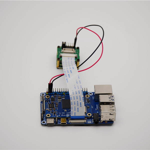
The ADP-MV1 is connected to the OrangePi CM4 via a 15-pin FFC cable with opposite surface alignment; please pay attention to the orientation of the contact surfaces.
  
===github库介绍===
+
Note that only the CAM1 shown in the image below supports MV and RAW cameras.[[File:OrangePi CM4 to MV cam.jpg|center|thumb|600x600px|OrangePi CM4 to MV cam|link=http://wiki.veye.cc/index.php/File:OrangePi_CM4_to_MV_cam.jpg]][[File:OrangePi CM4 to RAW cam.jpg|center|thumb|600x600px|OrangePi CM4 to RAW cam|link=http://wiki.veye.cc/index.php/File:OrangePi_CM4_to_RAW_cam.jpg]]<br />
 +
====Camera Connection to Orange Pi CM5====
 +
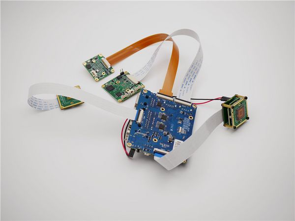
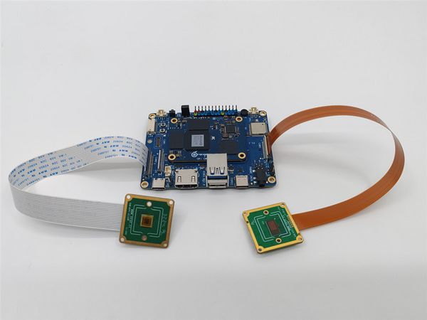
The OrangePi CM5 supports up to four cameras. The following diagram shows the hardware connection method for simultaneously connecting multiple cameras.[[File:OrangePi CM5 to all cam overview.jpg|center|thumb|600x600px|OrangePi CM5 to all cam overview|link=http://wiki.veye.cc/index.php/File:OrangePi_CM5_to_all_cam_overview.jpg]][[File:OrangePi CM5 to all cam backview.jpg|center|thumb|600x600px|OrangePi CM5 to all cam backview|link=http://wiki.veye.cc/index.php/File:OrangePi_CM5_to_all_cam_backview.jpg]]
 +
===Introduction to github repositories===
 
https://github.com/veyeimaging/rk35xx_veye_bsp
 
https://github.com/veyeimaging/rk35xx_veye_bsp
  
 
https://github.com/veyeimaging/rk35xx_orangepi
 
https://github.com/veyeimaging/rk35xx_orangepi
  
包括以下主要内容:
+
includes:
  
*driver和dts源码
+
*driver source code
*i2c通信工具集
+
*i2c toolkits
*应用层demo
+
*application demo
  
此外,在[https://github.com/veyeimaging/rk35xx_orangepi/releases releases]中,提供了编译好的烧写镜像和linux内核的deb安装包。
+
In addition, a compiled linux kernel installation package  is provided in the [https://github.com/veyeimaging/rk35xx_orangepi/releases releases].
===更新主板的Ubuntu系统===
+
===Upgrade the Ubuntu system===
我们提供了发布系统的烧写镜像,同时提供了linux内核的deb安装包。
+
We provide a flashing image for the release system, as well as a deb package for the Linux kernel.
  
参考OrangePi CM4[http://www.orangepi.cn/orangepiwiki/index.php/Orange_Pi_CM4 用户手册],或者OrangePi CM5的[http://www.orangepi.cn/html/hardWare/computerAndMicrocontrollers/service-and-support/Orange-Pi-CM5.html 用户手册]烧写系统。当然,也可以使用通用的dpkg命令,安装deb包。
+
Refer to the [http://www.orangepi.org/orangepiwiki/index.php/Orange_Pi_CM4 OrangePi CM4 user manual] or the [http://www.orangepi.org/html/hardWare/computerAndMicrocontrollers/service-and-support/Orange-Pi-CM5.html OrangePi CM5 user manual] for instructions on flashing the system. Alternatively, you can use the general <code>dpkg</code> command to install the deb package.
===系统状态检测===
+
===Check system status===
完成系统安装后,系统上电。在主板端执行以下命令来检测是否正确连接相机。
+
Run the following command to confirm whether the camera is probed.
  
 
<code>sudo dmesg | grep mvcam</code>
 
<code>sudo dmesg | grep mvcam</code>
 
====CM4====
 
====CM4====
CM4只支持通过cam1接口,接入相机。以RAW-MIPI-SC132M为例,dmesg信息中包含如下内容
+
The CM4 supports camera connection only through the CAM1 interface. Taking the RAW-MIPI-SC132M as an example, the <code>dmesg</code> output contains the following information:
 +
 
 +
The output message appears as shown below:
  
 
<code>mvcam 1-003b: camera is: RAW-MIPI-SC132M</code>
 
<code>mvcam 1-003b: camera is: RAW-MIPI-SC132M</code>
Line 93: Line 92:
 
<code>mvcam 1-003b: firmware version: 0x1040000</code>
 
<code>mvcam 1-003b: firmware version: 0x1040000</code>
  
执行如下命令,检查video设备节点
+
*Run the following command to check the presence of video node.
  
 
<code>ls /dev/video0</code>
 
<code>ls /dev/video0</code>
  
可以看到
+
The output message appears as shown below.
  
 
<code>video0</code>
 
<code>video0</code>
  
正确识别摄像头之后,相机被识别为/dev/video0。
+
==== CM5 ====
====CM5====
+
The CM5 supports the connection of up to four cameras. Taking the RAW-MIPI-SC132M as an example, the <code>dmesg</code> output contains the following information:
CM5 支持接入4个相机,以RAW-MIPI-SC132M为例,dmesg信息中包含如下内容dmesg信息中包含如下内容:


<code>mvcam 3-003b: camera is: RAW-MIPI-SC132M</code>
 
<code>mvcam 3-003b: camera is: RAW-MIPI-SC132M</code>
Line 120: Line 118:
  
 
<code>mvcam 6-003b: firmware version: 0x1040000</code>
 
<code>mvcam 6-003b: firmware version: 0x1040000</code>
====使用media-ctl查看拓扑结构====
 
下面以CM5的CAM1为例进行解释。
 
  
使用media-ctl指令,可以清晰的展现出当前的拓扑结构。
+
==== Viewing the Topology with <code>media-ctl</code> ====
 +
Let's take CM5's CAM1 as an example for explanation.
 +
 
 +
By using the <code>media-ctl</code> command, you can clearly display the current topology.
  
 
<code>media-ctl -p -d /dev/media2</code>
 
<code>media-ctl -p -d /dev/media2</code>
=====链接关系=====
+
 
 +
=====Link relationship=====
 
mv camera->rockchip-csi2-dphy1->rockchip-mipi-csi2->stream_cif_mipi_id0 - - ->DDR(/dev/video22)
 
mv camera->rockchip-csi2-dphy1->rockchip-mipi-csi2->stream_cif_mipi_id0 - - ->DDR(/dev/video22)
  
应用程序可以通过/dev/video22节点获取图像。
+
The application can obtain images through the <code>/dev/video22</code> node.
  
=====mv camera entity信息=====
+
===== mv camera entity information =====
以RAW-MIPI-SC132M为例:
+
Taking the RAW-MIPI-SC132M as an example:
  
 
<code>- entity 63: m00_b_mvcam 4-003b (1 pad, 1 link)</code>
 
<code>- entity 63: m00_b_mvcam 4-003b (1 pad, 1 link)</code>
Line 146: Line 146:
 
<code>                -> "rockchip-csi2-dphy1":0 [ENABLED]</code>
 
<code>                -> "rockchip-csi2-dphy1":0 [ENABLED]</code>
  
可以看到:
+
You can see that:
 
 
*该Entity完整的名称是: <code>m00_b_mvcam 4-003b</code>。
 
*它是一个 V4L2 subdev (Sub-Device) Sensor。
 
*它对应的节点是 <code>/dev/v4l-subdev8</code> ,应用程序(如<code>v4l2-ctl</code>)可以打开它,并进行配置。
 
*它的输出格式是 [<code>fmt:Y8_1X8/1080x1280@100/12000 field:none</code>] ,其中<code>Y8_1X8</code>是一种mbus-code的简写,下一小节会列出支持的mbus-code。
 
*当前分辨率是<code>1080x1280。</code>
 
*当前帧间隔是<code>100/12000</code>,即帧率是100。
 
  
摄像机输出的数据格式,可以通过media-ctl指令修改。
+
*The complete name of this entity is: <code>m00_b_mvcam 4-003b</code>.
 +
*It is a V4L2 subdev (Sub-Device) Sensor.
 +
*Its corresponding node is <code>/dev/v4l-subdev8</code>, which can be opened and configured by applications (such as <code>v4l2-ctl</code>).
 +
*Its output format is <code>[fmt:Y8_1X8/1080x1280@100/12000 field:none]</code>, where <code>Y8_1X8</code> is a shorthand for a mbus-code, which will be listed in the next section of this article.
 +
*The current resolution is <code>1080x1280</code>.
 +
*The current frame interval is <code>100/12000</code>, which means the frame rate is 120.
 +
*The data format output by the camera can be modified using the media-ctl command.
  
各个信息对应关系如下表:
+
The correspondence of the various information is as follows:
  
 
- CM4
 
- CM4
Line 211: Line 210:
 
|/dev/v4l-subdev2
 
|/dev/v4l-subdev2
 
|}
 
|}
====相机支持的mbus-code====
+
=====mbus-code list=====
MV系列和RAW系列相机具备不同的数据格式能力,具体请参考每个型号的相机的数据手册。
+
MV series and RAW series cameras have different data format capabilities, which can be found in the data manual for each camera model.
 
{| class="wikitable"
 
{| class="wikitable"
|+格式对应关系
 
 
!Format on datasheet
 
!Format on datasheet
 
!mbus-code for media-ctl
 
!mbus-code for media-ctl
Line 235: Line 233:
 
|UYVY
 
|UYVY
 
|}
 
|}
===raw图片格式说明===
+
===Raw data format===
RK35xx的VICAP模块支持两种数据保存格式,Compact和Noncompact RAW。可以通过RKCIF的RKCIF_CMD_SET_CSI_MEMORY_MODE ioctl指令修改模式。默认情况下,输出的是Compact RAW格式。[[File:Compact raw and noncompact raw of rk3588 vicap.png|center|thumb|800x800px|Compact raw and noncompact raw of rk3588 VICAP|link=http://wiki.veye.cc/index.php/File:Compact_raw_and_noncompact_raw_of_rk3588_vicap.png]]<br />
+
The VICAP module of RK3588 supports two data saving formats, Compact and Noncompact RAW. You can modify the mode using the RKCIF_CMD_SET_CSI_MEMORY_MODE ioctl command of RKCIF. By default, the output is in Compact RAW format.[[File:Compact raw and noncompact raw of rk3588 vicap.png|center|thumb|800x800px|Compact raw and noncompact raw of rk3588 VICAP|link=http://wiki.veye.cc/index.php/File:Compact_raw_and_noncompact_raw_of_rk3588_vicap.png]]
====具有填充位的图片格式(Noncompact RAW)====
+
====Noncompact RAW====
对于10bit深度、12bit深度的像素数据,总是使用两个字节来存储一个像素。这种存储方式方便软件处理,缺点是空间占用较大。根据数据有效数据保存在高位还是低位,又分为high align和low align两种。
+
For pixel data with 10-bit depth or 12-bit depth, two bytes are always used to store one pixel. This storage method is convenient for software processing, but it has the disadvantage of occupying a large amount of space.
 +
 
 +
Depending on whether the effective data is stored in the high bits or low bits, it can be further divided into two types: high align and low align.
 
=====Noncompact RAW(high align)=====
 
=====Noncompact RAW(high align)=====
数据保存到高位,用不到的低位以0填充。RK VICAP支持的一种数据格式。
+
Data is saved to the high bits, and the unused low bits are filled with 0. This is one of the data formats supported by RK VICAP.
 
=====Noncompact RAW(low align)=====
 
=====Noncompact RAW(low align)=====
数据保存到低位,用不到的高位以0填充。V4L2标准的'Y10 ' (10-bit Greyscale),'Y12 ' (12-bit Greyscale)格式都是以这种方式存储的。
+
In Noncompact RAW (low align) format, data is saved to the low bits, and the unused high bits are filled with 0. The V4L2 standard 'Y10' (10-bit Greyscale) and 'Y12' (12-bit Greyscale) formats are both stored in this way.
  
后文提到的pixel_layer_convert转换工具,也是将Compact RAW转换为此种存储方式。方便使用图片播放器打开显示。
+
The pixel_layer_convert conversion tool mentioned later in the article also converts Compact RAW to this storage format for easy display using image players.
====紧密排列的图片格式(Compact RAW)====
+
====Compact RAW====
如上图所示,像素和像素之间不会进行空bit位填充。
+
As shown above,there is no bit padding between pixels in this storage format.
====行对齐(line stride)====
+
====Line stride====
为了方便对图像进行快速操作,系统通常为每行数据提供行对齐的buffer大小。RK3588使用256字节对齐。
+
To facilitate fast operations on images, the system usually provides row-aligned buffer sizes for each line of data. RK3588 uses 256-byte alignment for this purpose.
  
 
line_stride = ALIGN_UP(image_width*bits_per_pixel/8,256)
 
line_stride = ALIGN_UP(image_width*bits_per_pixel/8,256)
  
比如当图像宽度是1456时:
+
For example, when the image width is 1456:
  
8bit depth,line_stride=1536。
+
8bit depth,line_stride=1536
  
10bit depth,preferred_stride=2048。
+
10bit depth,preferred_stride=2048
  
12bit depth,preferred_stride=2304。
+
12bit depth,preferred_stride=2304
====转换工具====
+
====Format convert tool====
我们编写了一个小工具:[https://github.com/veyeimaging/pixel_layer_convert pixel_layer_convert],可以很方便的将紧密排列的图片(Compact RAW)转为具有填充位的图片(Noncompact RAW(low align))。
+
We have written a small tool: [https://github.com/veyeimaging/pixel_layer_convert pixel_layer_convert], which can easily convert Compact images to Noncompact (low align) images.
  
比如下面的命令,可以将一个1456宽度的compact raw10 图片转为noncompact raw10。
+
For example, the following command can convert a Compact RAW10 image with a width of 1456 to Noncompact RAW10 format:
  
 
<code>./pixel_layer_convert -I R10C -i y10-1456x1088_0001.raw -o y10-1456x1088_0001_new.raw -w 1456</code>
 
<code>./pixel_layer_convert -I R10C -i y10-1456x1088_0001.raw -o y10-1456x1088_0001_new.raw -w 1456</code>
====raw图片播放器====
+
====Raw data image player====
推荐使用[https://www.offminor.de/ vooya]作为播放器,支持GREY, 和具有填充位的图片格式。
+
We recommend using [https://www.offminor.de/ vooya] as the player, which supports GREY, and unpacked image formats.
 +
 
 +
Also, y8 file can be used with this player: [https://yuv-player-deluxe.software.informer.com/2.6/ YUV Displayer Deluxe].
  
Y8文件可以用这个播放器: [https://yuv-player-deluxe.software.informer.com/2.6/ YUV Displayer Deluxe]。
+
=== Application Example ===
===应用范例===
+
Please note that in the following sections, <code>/dev/media0</code>, <code>/dev/video0</code>, and <code>/dev/v4l-subdev2</code> should be replaced with the actual values as described in the previous sections.
请注意,下面章节中的<code>/dev/media0</code>,<code>/dev/video0</code>,<code>/dev/v4l-subdev2</code>根据实际需要替换为前面章节的描述进行替换。
 
  
====配置命令行全局变量====
+
==== Configuring Global Variables ====
根据主板型号,配置I2C_BUS全局变量。
+
Set the <code>I2C_BUS</code> global variable based on the board model. Below are examples for two different boards, each with one camera as an example.
  
 
*OrangePi CM4
 
*OrangePi CM4
Line 283: Line 284:
 
<code>export I2C_BUS=6</code>
 
<code>export I2C_BUS=6</code>
  
为了后面描述方便,此处根据sensor尺寸,配置全局变量。
+
For the convenience of later descriptions, global variables are configured here according to the sensor size.
  
 
*MV-MIPI-IMX178M
 
*MV-MIPI-IMX178M
Line 364: Line 365:
  
 
<code>export FPS=50</code>
 
<code>export FPS=50</code>
====使用v4l2-ctl配置参数====
+
====Configure parameters using v4l2-ctl====
 
<code>$ v4l2-ctl -d /dev/v4l-subdev2 -L</code>
 
<code>$ v4l2-ctl -d /dev/v4l-subdev2 -L</code>
  
Line 381: Line 382:
 
<code>                          roi_y 0x00981906 (int)    : min=0 max=1024 step=4 default=0 value=0</code>
 
<code>                          roi_y 0x00981906 (int)    : min=0 max=1024 step=4 default=0 value=0</code>
  
可以使用下面的方法设置和获取参数。
+
Parameters can be set and get using the following methods.
  
<code>v4l2-ctl -d /dev/v4l-subdev2 --set-ctrl [ctrl_type]=[val]</code>
+
<code>v4l2-ctl --set-ctrl [ctrl_type]=[val]</code>
  
<code>v4l2-ctl -d /dev/v4l-subdev2 --get-ctrl [ctrl_type]</code>
+
<code>v4l2-ctl --get-ctrl [ctrl_type]</code>
  
以上所有功能,均可使用mv_mipi_i2c.sh实现。
+
All the above functions can be implemented using [[Mv mipi i2c.sh user guide|mv_mipi_i2c.sh]].
  
需要指出的是,以上参数在取图过程中均不可修改。下面进行逐个说明:
+
Note that the above parameters cannot be modified during the capture process.
=====配置触发模式=====
 
<code>v4l2-ctl -d /dev/v4l-subdev2 --set-ctrl <small>trigger_mode=[0-2]</small></code>
 
  
0:流模式
+
The following is an explanation of each parameter:
 +
=====Trigger Mode=====
 +
<code>v4l2-ctl --set-ctrl <small>trigger_mode=[0-2]</small></code>
  
1:普通触发模式
+
0:Video streaming mode
  
2:快速连续触发模式
+
1:Normal trigger mode.
=====配置触发源=====
 
<code>v4l2-ctl -d /dev/v4l-subdev2 --set-ctrl <small>trigger_src=[0-1]</small></code>
 
  
0: 软触发
+
2:High-speed continuous trigger mode.
 +
=====Trigger Source=====
 +
<code>v4l2-ctl --set-ctrl <small>trigger_src=[0-1]</small></code>
  
1: 硬触发
+
0: Software trigger mode.
=====软触发一次=====
+
 
<code>v4l2-ctl -d /dev/v4l-subdev2 --set-ctrl <small>soft_trgone=1</small></code>
+
1: Hardware trigger mode.
=====设置帧率=====
+
=====Software trigger command=====
<code>v4l2-ctl -d /dev/v4l-subdev2 --set-ctrl frame_rate=[1-max]</code>
+
<code>v4l2-ctl --set-ctrl <small>soft_trgone=1</small></code>
 +
=====Set frame rate=====
 +
<code>v4l2-ctl --set-ctrl frame_rate=[1-max]</code>
  
随分辨率的调整,最大帧率会自动更新。
+
The maximum frame rate is automatically updated as the resolution changed.
=====设置ROI起始位置=====
+
=====Set the starting position of the ROI=====
 
<code>v4l2-ctl -d /dev/v4l-subdev2 --set-ctrl roi_x=0</code>
 
<code>v4l2-ctl -d /dev/v4l-subdev2 --set-ctrl roi_x=0</code>
  
 
<code>v4l2-ctl -d /dev/v4l-subdev2 --set-ctrl roi_y=0</code>
 
<code>v4l2-ctl -d /dev/v4l-subdev2 --set-ctrl roi_y=0</code>
  
ROI其实位置设置之后,需要通过<code>media-ctl</code>命令完成完整的ROI配置。
+
After setting the ROI starting position, you need to complete the full ROI configuration using the <code>media-ctl</code> command.
  
设置roi后,最大帧率会自动调整。请注意,摄像机roi参数需要符合摄像机手册中的要求。
+
Note that setting the ROI may affect the maximum frame rate, and the ROI parameters need to meet the requirements specified in the camera manual.
====使用media-ctl配置图像格式====
+
====Set image format using media-ctl====
可以通过下面的命令,配置摄像机的数据格式,分辨率,帧率。
+
use the following command to configure the camera's data format, resolution, and frame rate using <code>media-ctl</code>:
  
 
<code>media-ctl -d /dev/media0 --set-v4l2 '"m00_b_mvcam '"$I2C_BUS"'-003b":0[fmt:Y8_1X8/'"$WIDTH"'x'"$HEIGHT"'@1/'"$FPS"']'</code>
 
<code>media-ctl -d /dev/media0 --set-v4l2 '"m00_b_mvcam '"$I2C_BUS"'-003b":0[fmt:Y8_1X8/'"$WIDTH"'x'"$HEIGHT"'@1/'"$FPS"']'</code>
  
其中:<code>"m00_b_mvcam 7-003b"</code>指的相机的<code>entity</code>完整名称,<code>Y8_1X8</code>为<code>mbus-code</code>,<code>'"$WIDTH"'x'"$HEIGHT"'</code>指明了分辨率,<code>1/'"$FPS"'</code>指明了帧率。
+
Among them: <code>"m00_b_mvcam '"$I2C_BUS"'-003b"</code> refers to the complete name of the camera entity, <code>Y8_1X8</code> is the mbus-code, <code>'"$WIDTH"'x'"$HEIGHT"'</code> indicates the resolution, <code>1/'"$FPS"'</code> indicates the resolution frame rate.
  
此处的width和height配合v4l2-ctl命令的<code>roi_x</code>和<code>roi_y</code>共同组成了ROI参数。
+
The width and height here cooperate with the roi_x and roi_y of the v4l2-ctl command to form the ROI parameter.
  
比如,对于MV-MIPI-IMX296M,这个命令经过变量替换后的结果是:
+
For example, for MV-MIPI-IMX296M, the command after variable replacement would be:
  
<code>media-ctl -d /dev/media0 --set-v4l2 '"m00_b_mvcam 7-003b":0[fmt:Y8_1X8/1456x1088@1/60 field:none]'</code>
+
<code>media-ctl -d /dev/media0 --set-v4l2 '"m00_b_mvcam 6-003b":0[fmt:Y8_1X8/1456x1088@1/60 field:none]'</code>
  
不仅可以在一个命令中同时配置数据格式,分辨率,帧率,也可以单独修改某一项或某几项。
+
You can not only configure the data format, resolution, and frame rate in one command, but also modify them separately as needed.
====流模式====
+
====Video Streaming mode====
=====设置数据格式,分辨率,帧率=====
+
=====Set data format, resolution, frame rate=====
 
<code>v4l2-ctl -d /dev/v4l-subdev2 --set-ctrl roi_x=0</code>
 
<code>v4l2-ctl -d /dev/v4l-subdev2 --set-ctrl roi_x=0</code>
  
Line 439: Line 442:
  
 
<code>media-ctl -d /dev/media0 --set-v4l2 '"m00_b_mvcam '"$I2C_BUS"'-003b":0[fmt:Y8_1X8/'"$WIDTH"'x'"$HEIGHT"'@1/'"$FPS"']'</code>
 
<code>media-ctl -d /dev/media0 --set-v4l2 '"m00_b_mvcam '"$I2C_BUS"'-003b":0[fmt:Y8_1X8/'"$WIDTH"'x'"$HEIGHT"'@1/'"$FPS"']'</code>
=====帧率统计=====
+
=====Frame rate statistics=====
<code>v4l2-ctl -d /dev/video0 --set-fmt-video=width=$WIDTH,height=$HEIGHT,pixelformat=GREY --stream-mmap --stream-count=-1 --stream-to=/dev/null</code>
+
In streaming mode, the following commands can be used for frame rate statistics:
  
或者
+
<code>v4l2-ctl --set-fmt-video=width=$WIDTH,height=$HEIGHT,pixelformat=GREY --stream-mmap --stream-count=-1 --stream-to=/dev/null</code>
  
<code>./yavta -c-1 --skip 0 -f Y8 -s ${WIDTH}x${HEIGHT} /dev/video0</code>
+
Or:
=====保存图片到文件=====
 
  
*raw8格式
+
<code>./yavta -c1000 --skip 0 -f Y8 -s ${WIDTH}x${HEIGHT} /dev/video0</code>
 +
=====Save image to file=====
 +
 
 +
*raw8
  
 
<code>v4l2-ctl -d /dev/video0 --set-fmt-video=width=$WIDTH,height=$HEIGHT,pixelformat=GREY --stream-mmap --stream-count=1 --stream-to=y8-${WIDTH}x${HEIGHT}.raw</code>
 
<code>v4l2-ctl -d /dev/video0 --set-fmt-video=width=$WIDTH,height=$HEIGHT,pixelformat=GREY --stream-mmap --stream-count=1 --stream-to=y8-${WIDTH}x${HEIGHT}.raw</code>
  
*raw10格式
+
*raw10
  
 
<code>v4l2-ctl -d /dev/video0 --set-fmt-video=width=$WIDTH,height=$HEIGHT,pixelformat='Y10 ' --stream-mmap --stream-count=1 --stream-to=y10-${WIDTH}x${HEIGHT}.raw</code>
 
<code>v4l2-ctl -d /dev/video0 --set-fmt-video=width=$WIDTH,height=$HEIGHT,pixelformat='Y10 ' --stream-mmap --stream-count=1 --stream-to=y10-${WIDTH}x${HEIGHT}.raw</code>
  
*raw12格式
+
*raw12
  
 
<code>v4l2-ctl -d /dev/video0 --set-fmt-video=$WIDTH,height=$HEIGHT,pixelformat='Y12 ' --stream-mmap --stream-count=1 --stream-to=y12-${WIDTH}x${HEIGHT}.raw</code>
 
<code>v4l2-ctl -d /dev/video0 --set-fmt-video=$WIDTH,height=$HEIGHT,pixelformat='Y12 ' --stream-mmap --stream-count=1 --stream-to=y12-${WIDTH}x${HEIGHT}.raw</code>
  
图片格式请参考前面章节的描述。
+
Please refer to the description in the previous section for the image format.
=====yavta应用范例=====
+
=====Example of yavta=====
======yavta安装======
+
======Install yavta======
 
<code>git clone <nowiki>git://git.ideasonboard.org/yavta.git</nowiki></code>
 
<code>git clone <nowiki>git://git.ideasonboard.org/yavta.git</nowiki></code>
  
 
<code>cd yavta;make</code>
 
<code>cd yavta;make</code>
======保存图片到文件======
+
======Save image to file======
配置完数据格式,分辨率,帧率之后,执行:
+
After setting data format, resolution, frame rate,run:
  
 
<code>./yavta -c1 -Fy8-${WIDTH}x${HEIGHT}.raw --skip 0 -f Y8 -s ${WIDTH}x${HEIGHT} /dev/video0</code>
 
<code>./yavta -c1 -Fy8-${WIDTH}x${HEIGHT}.raw --skip 0 -f Y8 -s ${WIDTH}x${HEIGHT} /dev/video0</code>
=====将相机数据导入OpenCV的范例=====
+
=====Example of import image to OpenCV=====
 
<code>sudo apt install python3-opencv</code>
 
<code>sudo apt install python3-opencv</code>
  
详见github上的[https://github.com/veyeimaging/rk356x_firefly/tree/main/linux/samples samples]目录。
+
See the [https://github.com/veyeimaging/rk356x_firefly/tree/main/linux/samples samples] directory on github for details.
 
 
<code>python3 ./v4l2dev_2_opencv_show_grey.py --width 1456 --height 1088 --fps 60 --i2c 7</code>
 
  
注意需要使用合适的参数来执行上述程序。
+
<code>python ./v4l2dev_2_opencv_show_grey.py --width 1456 --height 1088 --fps 60 --i2c 7</code>
=====gstreamer应用范例=====
+
=====Example of gstreamer application=====
我们提供了几个gstreamer例程,实现了预览功能。详见github上的[https://github.com/veyeimaging/rk35xx_veye_bsp/tree/main/samples samples]目录。
+
We provide several gstreamer routines that implement the preview function. See the [https://github.com/veyeimaging/rk35xx_veye_bsp/tree/main/samples samples] directory on github for details.
====触发模式====
+
====Trigger mode====
=====设置数据格式,分辨率,帧率=====
+
=====Set data format, resolution, frame rate=====
 
<code>v4l2-ctl -d /dev/v4l-subdev2 --set-ctrl roi_x=0</code>
 
<code>v4l2-ctl -d /dev/v4l-subdev2 --set-ctrl roi_x=0</code>
  
Line 486: Line 489:
  
 
<code>media-ctl -d /dev/media0 --set-v4l2 '"m00_b_mvcam '"$I2C_BUS"'-003b":0[fmt:Y8_1X8/'"$WIDTH"'x'"$HEIGHT"'@1/'"$FPS"']'</code>
 
<code>media-ctl -d /dev/media0 --set-v4l2 '"m00_b_mvcam '"$I2C_BUS"'-003b":0[fmt:Y8_1X8/'"$WIDTH"'x'"$HEIGHT"'@1/'"$FPS"']'</code>
=====软触发模式=====
+
=====Software trigger mode=====
======设置模式======
+
======Set mode======
 
<code>v4l2-ctl -d /dev/v4l-subdev2 --set-ctrl <small>trigger_mode=1</small></code>
 
<code>v4l2-ctl -d /dev/v4l-subdev2 --set-ctrl <small>trigger_mode=1</small></code>
  
 
<code>v4l2-ctl -d /dev/v4l-subdev2 --set-ctrl <small>trigger_src=0</small></code>
 
<code>v4l2-ctl -d /dev/v4l-subdev2 --set-ctrl <small>trigger_src=0</small></code>
======开始取图======
+
======Start acquisition======
 
<code>v4l2-ctl -d /dev/video0 --set-fmt-video=width=$WIDTH,height=$HEIGHT,pixelformat=GREY --stream-mmap --stream-count=1 --stream-to=y8-${WIDTH}x${HEIGHT}.raw</code>
 
<code>v4l2-ctl -d /dev/video0 --set-fmt-video=width=$WIDTH,height=$HEIGHT,pixelformat=GREY --stream-mmap --stream-count=1 --stream-to=y8-${WIDTH}x${HEIGHT}.raw</code>
======进行软触发操作======
+
======Perform soft trigger operation======
在其他的shell终端,可以多次执行下面命令进行多次触发。
+
In other shell terminals, you can execute the following command multiple times for multiple triggers.
  
 
<code>v4l2-ctl -d /dev/v4l-subdev2 --set-ctrl <small>soft_trgone=1</small></code>
 
<code>v4l2-ctl -d /dev/v4l-subdev2 --set-ctrl <small>soft_trgone=1</small></code>
=====硬触发模式=====
+
=====Hardware trigger mode=====
======设置模式======
+
======Set mode======
 
<code>v4l2-ctl -d /dev/v4l-subdev2 --set-ctrl <small>trigger_mode=1</small></code>
 
<code>v4l2-ctl -d /dev/v4l-subdev2 --set-ctrl <small>trigger_mode=1</small></code>
  
 
<code>v4l2-ctl -d /dev/v4l-subdev2 --set-ctrl <small>trigger_src=1</small></code>
 
<code>v4l2-ctl -d /dev/v4l-subdev2 --set-ctrl <small>trigger_src=1</small></code>
  
可以使用[[Mv mipi i2c.sh user guide|mv_mipi_i2c.sh]]脚本进行丰富的触发参数设置。
+
The [[Mv mipi i2c.sh user guide|mv_mipi_i2c.sh]] script can be used to set rich trigger parameters.
======开始取图======
+
======Start acquisition======
 
<code>v4l2-ctl -d /dev/video0 --set-fmt-video=width=$WIDTH,height=$HEIGHT,pixelformat=GREY --stream-mmap --stream-count=1 --stream-to=y8-${WIDTH}x${HEIGHT}.raw</code>
 
<code>v4l2-ctl -d /dev/video0 --set-fmt-video=width=$WIDTH,height=$HEIGHT,pixelformat=GREY --stream-mmap --stream-count=1 --stream-to=y8-${WIDTH}x${HEIGHT}.raw</code>
======进行硬触发操作======
+
======Perform hardware trigger operation======
将合适的触发信号连接到摄像机的trigger引脚并进行触发。
+
Connect the appropriate trigger signal to the trigger pin of the camera and trigger it.
===i2c脚本使用说明===
+
===i2c script for parameter configuration===
我们提供了shell脚本来配置参数。
+
We provide shell scripts to configure the parameters.
  
 
[[mv_mipi_i2c.sh user guide]]
 
[[mv_mipi_i2c.sh user guide]]
===参考资料===
+
===References===
  
 
*OrangePi CM4
 
*OrangePi CM4
Line 521: Line 524:
  
 
http://www.orangepi.cn/html/hardWare/computerAndMicrocontrollers/service-and-support/Orange-Pi-CM5.html
 
http://www.orangepi.cn/html/hardWare/computerAndMicrocontrollers/service-and-support/Orange-Pi-CM5.html
===本文修改记录===
+
===Document History===
  
*2025-01-09
+
*2024-01-10
  
发布第一个版本。
+
Release 1st version.

Latest revision as of 14:32, 10 January 2025

查看中文

1 Overview

The MV series and RAW series cameras are cameras designed for AI applications in the industrial field. They use the MIPI CSI-2 interface and are particularly suitable for use with embedded computing platforms. They have rich data formats and triggering features, extremely low latency, high bandwidth, and reliable stability.

This article takes OrangePi CM4 and OrangePi CM5 board as an example to introduce how to connect MV and RAW series cameras to the RK3566/3K3568 and RK3588S/RK3588 system.

We provide drivers for the Linux operating system (using Ubuntu as an example).

1.1 Camera Module List

Series Model Status
MV series MV-MIPI-IMX178M Done
MV series MV-MIPI-SC130M Done
MV series MV-MIPI-IMX296M Done
MV series MV-MIPI-IMX287M Done
MV series MV-MIPI-IMX265M Done
MV series MV-MIPI-IMX264M Done
RAW series RAW-MIPI-SC132M Done
RAW series RAW-MIPI-IMX462M Done
RAW series RAW-MIPI-AR0234M Done
RAW series RAW-MIPI-SC535M Done

2 Hardware Setup

We use the official baseboards of the Orange Pi CM4 and CM5, which feature a 15-pin header compatible with Raspberry Pi. For the RAW series cameras, our cameras can be directly mounted onto the baseboard without the need for an adapter board. For the MV series cameras, the ADP-MV1 adapter board is required for connection.

2.1 Camera Connection to Orange Pi CM4

The ADP-MV1 is connected to the OrangePi CM4 via a 15-pin FFC cable with opposite surface alignment; please pay attention to the orientation of the contact surfaces.

Note that only the CAM1 shown in the image below supports MV and RAW cameras.

OrangePi CM4 to MV cam
OrangePi CM4 to RAW cam


2.2 Camera Connection to Orange Pi CM5

The OrangePi CM5 supports up to four cameras. The following diagram shows the hardware connection method for simultaneously connecting multiple cameras.

OrangePi CM5 to all cam overview
OrangePi CM5 to all cam backview

3 Introduction to github repositories

https://github.com/veyeimaging/rk35xx_veye_bsp

https://github.com/veyeimaging/rk35xx_orangepi

includes:

  • driver source code
  • i2c toolkits
  • application demo

In addition, a compiled linux kernel installation package is provided in the releases.

4 Upgrade the Ubuntu system

We provide a flashing image for the release system, as well as a deb package for the Linux kernel.

Refer to the OrangePi CM4 user manual or the OrangePi CM5 user manual for instructions on flashing the system. Alternatively, you can use the general dpkg command to install the deb package.

5 Check system status

Run the following command to confirm whether the camera is probed.

sudo dmesg | grep mvcam

5.1 CM4

The CM4 supports camera connection only through the CAM1 interface. Taking the RAW-MIPI-SC132M as an example, the dmesg output contains the following information:

The output message appears as shown below:

mvcam 1-003b: camera is: RAW-MIPI-SC132M

mvcam 1-003b: firmware version: 0x1040000

  • Run the following command to check the presence of video node.

ls /dev/video0

The output message appears as shown below.

video0

5.2 CM5

The CM5 supports the connection of up to four cameras. Taking the RAW-MIPI-SC132M as an example, the dmesg output contains the following information:

mvcam 3-003b: camera is: RAW-MIPI-SC132M

mvcam 3-003b: firmware version: 0x1040000

mvcam 4-003b: camera is: RAW-MIPI-SC132M

mvcam 4-003b: firmware version: 0x1040000

mvcam 5-003b: camera is: RAW-MIPI-SC132M

mvcam 5-003b: firmware version: 0x1040000  

mvcam 6-003b: camera is: RAW-MIPI-SC132M

mvcam 6-003b: firmware version: 0x1040000

5.3 Viewing the Topology with media-ctl

Let's take CM5's CAM1 as an example for explanation.

By using the media-ctl command, you can clearly display the current topology.

media-ctl -p -d /dev/media2

5.3.1 Link relationship

mv camera->rockchip-csi2-dphy1->rockchip-mipi-csi2->stream_cif_mipi_id0 - - ->DDR(/dev/video22)

The application can obtain images through the /dev/video22 node.

5.3.2 mv camera entity information

Taking the RAW-MIPI-SC132M as an example:

- entity 63: m00_b_mvcam 4-003b (1 pad, 1 link)

             type V4L2 subdev subtype Sensor flags 0

             device node name /dev/v4l-subdev8

        pad0: Source

                [fmt:Y8_1X8/1080x1280@100/12000 field:none]

                -> "rockchip-csi2-dphy1":0 [ENABLED]

You can see that:

  • The complete name of this entity is: m00_b_mvcam 4-003b.
  • It is a V4L2 subdev (Sub-Device) Sensor.
  • Its corresponding node is /dev/v4l-subdev8, which can be opened and configured by applications (such as v4l2-ctl).
  • Its output format is [fmt:Y8_1X8/1080x1280@100/12000 field:none], where Y8_1X8 is a shorthand for a mbus-code, which will be listed in the next section of this article.
  • The current resolution is 1080x1280.
  • The current frame interval is 100/12000, which means the frame rate is 120.
  • The data format output by the camera can be modified using the media-ctl command.

The correspondence of the various information is as follows:

- CM4

CAM num I2C media node media entity name video node subdev node
1 1 /dev/media0 m00_b_mvcam 1-003b /dev/video0 /dev/v4l-subdev2

- CM5

CAM num I2C media node media entity name video node subdev node
1 4 /dev/media2 m00_b_mvcam 4-003b /dev/video22 /dev/v4l-subdev8
2 3 /dev/media3 m01_b_mvcam 3-003b /dev/video33 /dev/v4l-subdev11
3 5 /dev/media1 m00_b_mvcam 5-003b /dev/video11 /dev/v4l-subdev5
4 6 /dev/media0 m00_b_mvcam 6-003b /dev/video0 /dev/v4l-subdev2
5.3.3 mbus-code list

MV series and RAW series cameras have different data format capabilities, which can be found in the data manual for each camera model.

Format on datasheet mbus-code for media-ctl FourCC pixelformat for v4l2-ctl
RAW8 Y8_1X8 GREY
RAW10 Y10_1X10 'Y10 '
RAW12 Y12_1X12 'Y12 '
UYVY UYVY8_2X8 UYVY

6 Raw data format

The VICAP module of RK3588 supports two data saving formats, Compact and Noncompact RAW. You can modify the mode using the RKCIF_CMD_SET_CSI_MEMORY_MODE ioctl command of RKCIF. By default, the output is in Compact RAW format.

Compact raw and noncompact raw of rk3588 VICAP

6.1 Noncompact RAW

For pixel data with 10-bit depth or 12-bit depth, two bytes are always used to store one pixel. This storage method is convenient for software processing, but it has the disadvantage of occupying a large amount of space.

Depending on whether the effective data is stored in the high bits or low bits, it can be further divided into two types: high align and low align.

6.1.1 Noncompact RAW(high align)

Data is saved to the high bits, and the unused low bits are filled with 0. This is one of the data formats supported by RK VICAP.

6.1.2 Noncompact RAW(low align)

In Noncompact RAW (low align) format, data is saved to the low bits, and the unused high bits are filled with 0. The V4L2 standard 'Y10' (10-bit Greyscale) and 'Y12' (12-bit Greyscale) formats are both stored in this way.

The pixel_layer_convert conversion tool mentioned later in the article also converts Compact RAW to this storage format for easy display using image players.

6.2 Compact RAW

As shown above,there is no bit padding between pixels in this storage format.

6.3 Line stride

To facilitate fast operations on images, the system usually provides row-aligned buffer sizes for each line of data. RK3588 uses 256-byte alignment for this purpose.

line_stride = ALIGN_UP(image_width*bits_per_pixel/8,256)

For example, when the image width is 1456:

8bit depth,line_stride=1536

10bit depth,preferred_stride=2048

12bit depth,preferred_stride=2304

6.4 Format convert tool

We have written a small tool: pixel_layer_convert, which can easily convert Compact images to Noncompact (low align) images.

For example, the following command can convert a Compact RAW10 image with a width of 1456 to Noncompact RAW10 format:

./pixel_layer_convert -I R10C -i y10-1456x1088_0001.raw -o y10-1456x1088_0001_new.raw -w 1456

6.5 Raw data image player

We recommend using vooya as the player, which supports GREY, and unpacked image formats.

Also, y8 file can be used with this player: YUV Displayer Deluxe.

7 Application Example

Please note that in the following sections, /dev/media0, /dev/video0, and /dev/v4l-subdev2 should be replaced with the actual values as described in the previous sections.

7.1 Configuring Global Variables

Set the I2C_BUS global variable based on the board model. Below are examples for two different boards, each with one camera as an example.

  • OrangePi CM4

export I2C_BUS=1

  • OrangePi CM5

export I2C_BUS=6

For the convenience of later descriptions, global variables are configured here according to the sensor size.

  • MV-MIPI-IMX178M

export WIDTH=3088

export HEIGHT=2064

export FPS=22

  • MV-MIPI-SC130M

export WIDTH=1280

export HEIGHT=1024

export FPS=108

  • MV-MIPI-IMX296M

export WIDTH=1456

export HEIGHT=1088

export FPS=60

  • MV-MIPI-IMX287M

export WIDTH=704

export HEIGHT=544

export FPS=319

  • MV-MIPI-IMX265M

export WIDTH=2048

export HEIGHT=1544

export FPS=45

  • MV-MIPI-IMX264M

export WIDTH=2432

export HEIGHT=2056

export FPS=28

  • RAW-MIPI-SC132M

export WIDTH=1024

export HEIGHT=1280

export FPS=120

  • RAW-MIPI-IMX462M

export WIDTH=1920

export HEIGHT=1088

export FPS=60

  • RAW-MIPI-AR0234M

export WIDTH=1920

export HEIGHT=1200

export FPS=60

  • RAW-MIPI-SC535M

export WIDTH=2432

export HEIGHT=2048

export FPS=50

7.2 Configure parameters using v4l2-ctl

$ v4l2-ctl -d /dev/v4l-subdev2 -L

User Controls

                   trigger_mode 0x00981901 (int)    : min=0 max=2 step=1 default=0 value=0 flags=volatile, execute-on-write

                    trigger_src 0x00981902 (int)    : min=0 max=1 step=1 default=1 value=1 flags=volatile, execute-on-write

                    soft_trgone 0x00981903 (button) : flags=write-only, execute-on-write

                     frame_rate 0x00981904 (int)    : min=1 max=60 step=1 default=60 value=60 flags=volatile, execute-on-write

                          roi_x 0x00981905 (int)    : min=0 max=1376 step=8 default=0 value=0

                          roi_y 0x00981906 (int)    : min=0 max=1024 step=4 default=0 value=0

Parameters can be set and get using the following methods.

v4l2-ctl --set-ctrl [ctrl_type]=[val]

v4l2-ctl --get-ctrl [ctrl_type]

All the above functions can be implemented using mv_mipi_i2c.sh.

Note that the above parameters cannot be modified during the capture process.

The following is an explanation of each parameter:

7.2.1 Trigger Mode

v4l2-ctl --set-ctrl trigger_mode=[0-2]

0:Video streaming mode

1:Normal trigger mode.

2:High-speed continuous trigger mode.

7.2.2 Trigger Source

v4l2-ctl --set-ctrl trigger_src=[0-1]

0: Software trigger mode.

1: Hardware trigger mode.

7.2.3 Software trigger command

v4l2-ctl --set-ctrl soft_trgone=1

7.2.4 Set frame rate

v4l2-ctl --set-ctrl frame_rate=[1-max]

The maximum frame rate is automatically updated as the resolution changed.

7.2.5 Set the starting position of the ROI

v4l2-ctl -d /dev/v4l-subdev2 --set-ctrl roi_x=0

v4l2-ctl -d /dev/v4l-subdev2 --set-ctrl roi_y=0

After setting the ROI starting position, you need to complete the full ROI configuration using the media-ctl command.

Note that setting the ROI may affect the maximum frame rate, and the ROI parameters need to meet the requirements specified in the camera manual.

7.3 Set image format using media-ctl

use the following command to configure the camera's data format, resolution, and frame rate using media-ctl:

media-ctl -d /dev/media0 --set-v4l2 '"m00_b_mvcam '"$I2C_BUS"'-003b":0[fmt:Y8_1X8/'"$WIDTH"'x'"$HEIGHT"'@1/'"$FPS"']'

Among them: "m00_b_mvcam '"$I2C_BUS"'-003b" refers to the complete name of the camera entity, Y8_1X8 is the mbus-code, '"$WIDTH"'x'"$HEIGHT"' indicates the resolution, 1/'"$FPS"' indicates the resolution frame rate.

The width and height here cooperate with the roi_x and roi_y of the v4l2-ctl command to form the ROI parameter.

For example, for MV-MIPI-IMX296M, the command after variable replacement would be:

media-ctl -d /dev/media0 --set-v4l2 '"m00_b_mvcam 6-003b":0[fmt:Y8_1X8/1456x1088@1/60 field:none]'

You can not only configure the data format, resolution, and frame rate in one command, but also modify them separately as needed.

7.4 Video Streaming mode

7.4.1 Set data format, resolution, frame rate

v4l2-ctl -d /dev/v4l-subdev2 --set-ctrl roi_x=0

v4l2-ctl -d /dev/v4l-subdev2 --set-ctrl roi_y=0

media-ctl -d /dev/media0 --set-v4l2 '"m00_b_mvcam '"$I2C_BUS"'-003b":0[fmt:Y8_1X8/'"$WIDTH"'x'"$HEIGHT"'@1/'"$FPS"']'

7.4.2 Frame rate statistics

In streaming mode, the following commands can be used for frame rate statistics:

v4l2-ctl --set-fmt-video=width=$WIDTH,height=$HEIGHT,pixelformat=GREY --stream-mmap --stream-count=-1 --stream-to=/dev/null

Or:

./yavta -c1000 --skip 0 -f Y8 -s ${WIDTH}x${HEIGHT} /dev/video0

7.4.3 Save image to file
  • raw8

v4l2-ctl -d /dev/video0 --set-fmt-video=width=$WIDTH,height=$HEIGHT,pixelformat=GREY --stream-mmap --stream-count=1 --stream-to=y8-${WIDTH}x${HEIGHT}.raw

  • raw10

v4l2-ctl -d /dev/video0 --set-fmt-video=width=$WIDTH,height=$HEIGHT,pixelformat='Y10 ' --stream-mmap --stream-count=1 --stream-to=y10-${WIDTH}x${HEIGHT}.raw

  • raw12

v4l2-ctl -d /dev/video0 --set-fmt-video=$WIDTH,height=$HEIGHT,pixelformat='Y12 ' --stream-mmap --stream-count=1 --stream-to=y12-${WIDTH}x${HEIGHT}.raw

Please refer to the description in the previous section for the image format.

7.4.4 Example of yavta
7.4.4.1 Install yavta

git clone git://git.ideasonboard.org/yavta.git

cd yavta;make

7.4.4.2 Save image to file

After setting data format, resolution, frame rate,run:

./yavta -c1 -Fy8-${WIDTH}x${HEIGHT}.raw --skip 0 -f Y8 -s ${WIDTH}x${HEIGHT} /dev/video0

7.4.5 Example of import image to OpenCV

sudo apt install python3-opencv

See the samples directory on github for details.

python ./v4l2dev_2_opencv_show_grey.py --width 1456 --height 1088 --fps 60 --i2c 7

7.4.6 Example of gstreamer application

We provide several gstreamer routines that implement the preview function. See the samples directory on github for details.

7.5 Trigger mode

7.5.1 Set data format, resolution, frame rate

v4l2-ctl -d /dev/v4l-subdev2 --set-ctrl roi_x=0

v4l2-ctl -d /dev/v4l-subdev2 --set-ctrl roi_y=0

media-ctl -d /dev/media0 --set-v4l2 '"m00_b_mvcam '"$I2C_BUS"'-003b":0[fmt:Y8_1X8/'"$WIDTH"'x'"$HEIGHT"'@1/'"$FPS"']'

7.5.2 Software trigger mode
7.5.2.1 Set mode

v4l2-ctl -d /dev/v4l-subdev2 --set-ctrl trigger_mode=1

v4l2-ctl -d /dev/v4l-subdev2 --set-ctrl trigger_src=0

7.5.2.2 Start acquisition

v4l2-ctl -d /dev/video0 --set-fmt-video=width=$WIDTH,height=$HEIGHT,pixelformat=GREY --stream-mmap --stream-count=1 --stream-to=y8-${WIDTH}x${HEIGHT}.raw

7.5.2.3 Perform soft trigger operation

In other shell terminals, you can execute the following command multiple times for multiple triggers.

v4l2-ctl -d /dev/v4l-subdev2 --set-ctrl soft_trgone=1

7.5.3 Hardware trigger mode
7.5.3.1 Set mode

v4l2-ctl -d /dev/v4l-subdev2 --set-ctrl trigger_mode=1

v4l2-ctl -d /dev/v4l-subdev2 --set-ctrl trigger_src=1

The mv_mipi_i2c.sh script can be used to set rich trigger parameters.

7.5.3.2 Start acquisition

v4l2-ctl -d /dev/video0 --set-fmt-video=width=$WIDTH,height=$HEIGHT,pixelformat=GREY --stream-mmap --stream-count=1 --stream-to=y8-${WIDTH}x${HEIGHT}.raw

7.5.3.3 Perform hardware trigger operation

Connect the appropriate trigger signal to the trigger pin of the camera and trigger it.

8 i2c script for parameter configuration

We provide shell scripts to configure the parameters.

mv_mipi_i2c.sh user guide

9 References

  • OrangePi CM4

http://www.orangepi.cn/orangepiwiki/index.php/Orange_Pi_CM4

  • OrangePi CM5

http://www.orangepi.cn/html/hardWare/computerAndMicrocontrollers/service-and-support/Orange-Pi-CM5.html

10 Document History

  • 2024-01-10

Release 1st version.