|
|
| Line 156: |
Line 156: |
| | === Camera Application Development Guide === | | === Camera Application Development Guide === |
| | Application Development Guide | | Application Development Guide |
| − |
| |
| − | ===='''State Detection and Environment Variable Configuration'''====
| |
| − | [https://github.com/veyeimaging/rk35xx_veye_bsp/tree/main/mv_tools_rockchip/i2c_tools Here], We have provided two scripts that can automatically retrieve some information about the camera.
| |
| − |
| |
| − | First, try using the probe_camera_info-rk.sh script. This script is used to detect the connected and successfully registered camera devices, retrieve the corresponding media device nodes, video device nodes, sub-device nodes, I²C buses, and device identifiers and other low-level information. After execution, it will generate an auto_camera_index.json file in the current directory and record the retrieved information in the file.
| |
| − |
| |
| − | ./probe_camera_info-rk.sh
| |
| − |
| |
| − | cat auto_camera_index.json
| |
| − |
| |
| − | [
| |
| − |
| |
| − | {
| |
| − |
| |
| − | "media_node": "/dev/media0",
| |
| − |
| |
| − | "video_node": "/dev/video0",
| |
| − |
| |
| − | "video_subnode": "/dev/v4l-subdev2",
| |
| − |
| |
| − | "media_entity_name": "m00_b_gxcam 7-003b",
| |
| − |
| |
| − | "i2c_bus": "7"
| |
| − |
| |
| − | }
| |
| − |
| |
| − | ]
| |
| − |
| |
| − | By referring to the index information, we can see the "i2c_bus": "7" corresponding i2c_bus information, as well as the number of devices connected. The current index shows that only one device is connected, and the i2c_bus number is 7. If multiple devices are connected, the index information may include "i2c_bus": "10", "i2c_bus": "11" and so on. Then, using the gx_probe.sh script, if it is a multi-camera system, the i2c_bus can be executed based on the information read from the previous script, and the corresponding camera model, width, height, frame rate and other information can be configured in the environment variables.
| |
| − |
| |
| − | Usage:
| |
| − |
| |
| − | <code>source ./gx_probe.sh 7</code>
| |
| − |
| |
| − | A typical output:
| |
| − |
| |
| − | <code>$ source ./gx_probe.sh 7</code>
| |
| − |
| |
| − | <code>Found veye_gxcam camera on i2c-7.</code>
| |
| − |
| |
| − | <code>Setenv CAMERAMODEL = GX-MIPI-IMX662</code>
| |
| − |
| |
| − | <code>Setenv FPS = 60</code>
| |
| − |
| |
| − | <code>Setenv WIDTH = 1920</code>
| |
| − |
| |
| − | <code>Setenv HEIGHT = 1080</code>
| |
| − |
| |
| − | You can verify the environment variable output using:
| |
| − |
| |
| − | <code>echo $CAMERAMODEL</code>
| |
| − |
| |
| − | Note that these environment variables are only valid for the current session.
| |
| − | ====Configuring global variables====
| |
| − | Based on the board model, configure the I2C_BUS global variable as follows:
| |
| − |
| |
| − | * ROC-RK3588S-PC
| |
| − |
| |
| − | <code>export I2C_BUS=7</code>
| |
| − |
| |
| − | * ROC-RK3566-PC and ROC-RK3576-PC
| |
| − |
| |
| − | <code>export I2C_BUS=4</code>
| |
| − | ==== Using media-ctl to view topology ====
| |
| − | Using the media-ctl command can clearly display the current topography structure.
| |
| − |
| |
| − | <code>media-ctl -p -d /dev/media0</code>
| |
| − |
| |
| − | ===== Link relationship =====
| |
| − | gx camera->rockchip-csi2-dphy0->rockchip-mipi-csi2->stream_cif_mipi_id0 - - ->DDR(/dev/video0)
| |
| − |
| |
| − | The application can obtain images through the /dev/video0 node.
| |
| − |
| |
| − | ===== gx camera entity information =====
| |
| − | Taking the GX-MIPI-IMX662 as an example:
| |
| − |
| |
| − | <code>- entity 63: m00_b_gxcam 7-003b (1 pad, 1 link)</code>
| |
| − |
| |
| − | <code> type V4L2 subdev subtype Sensor flags 0</code>
| |
| − |
| |
| − | <code> device node name /dev/v4l-subdev2</code>
| |
| − |
| |
| − | <code> pad0: Source</code>
| |
| − |
| |
| − | <code> [fmt:UYVY8_2X8/1920x1080@10000/600000 field:none colorspace:rec709</code>
| |
| − |
| |
| − | <code> crop:(0,0)/1920x1080]</code>
| |
| − |
| |
| − | <code> -> "rockchip-csi2-dphy0":0 [ENABLED]</code>
| |
| − |
| |
| − | You can see that:
| |
| − |
| |
| − | * The complete name of this entity is: <code>m00_b_gxcam 7-003b</code>.(It is <code>m00_b_gxcam 4-003b</code>on ROC-RK3566-PC.)
| |
| − | * It is a V4L2 subdev (Sub-Device) Sensor.
| |
| − | * Its corresponding node is <code>/dev/v4l-subdev2</code>, which can be opened and configured by applications (such as <code>v4l2-ctl</code>).
| |
| − | * Its output format is <code>[fmt:UYVY8_2X8/1920x1080@100/6000 field:none]</code>, where <code>UYVY8_2X8</code> is a shorthand for a mbus-code, which will be listed in the next section of this article.
| |
| − | * The current resolution is <code>1920x1080</code>.
| |
| − | * The current frame interval is <code>100/6000</code>, which means the frame rate is 60.
| |
| − | * The data format output by the camera can be modified using the media-ctl command.
| |
| − |
| |
| − | ===== mbus-code list =====
| |
| − | GX series cameras have different data format capabilities, which can be found in the data manual for each camera model.
| |
| − | {| class="wikitable"
| |
| − | !Format on datasheet
| |
| − | !mbus-code for media-ctl
| |
| − | !FourCC pixelformat for v4l2-ctl
| |
| − | |-
| |
| − | |UYVY
| |
| − | |UYVY8_2X8
| |
| − | |UYVY
| |
| − | |}
| |
| − |
| |
| − | ==== veye_viewe工具 ====
| |
| − | It can be downloaded from [https://github.com/veyeimaging/veye_viewer veye_viewe]
| |
| − |
| |
| − | We can use this tool to configure some parameters of the camera (directly operate and change the parameters of the register), switch the mode (stream mode, trigger mode, synchronization mode), and view some basic information of the camera (resolution, frame rate, etc.)
| |
| − |
| |
| − | === Application examples ===
| |
| − | ==== Configure parameters using v4l2-ctl ====
| |
| − | <code>$ v4l2-ctl -d /dev/v4l-subdev2 -L</code>
| |
| − |
| |
| − | <code>User Controls</code>
| |
| − |
| |
| − | <code> trigger_mode 0x00981a01 (int) : min=0 max=4 step=1 default=0 value=0 flags=volatile, execute-on-write</code>
| |
| − |
| |
| − | <code> trigger_src 0x00981a02 (int) : min=0 max=1 step=1 default=1 value=1 flags=volatile, execute-on-write</code>
| |
| − |
| |
| − | <code> soft_trgone 0x00981a03 (button) : value=0 flags=write-only, execute-on-write</code>
| |
| − |
| |
| − | <code> sync_role 0x00981a04 (int) : min=0 max=1 step=1 default=0 value=0 flags=volatile, execute-on-write</code>
| |
| − |
| |
| − | <code> frame_rate 0x00981a05 (int) : min=0 max=60 step=1 default=60 value=60 flags=volatile, execute-on-write</code>
| |
| − |
| |
| − | Parameters can be set and get using the following methods.
| |
| − |
| |
| − | <code>v4l2-ctl -d /dev/v4l-subdev2 --set-ctrl [ctrl_type]=[val]</code>
| |
| − |
| |
| − | <code>v4l2-ctl -d /dev/v4l-subdev2 --get-ctrl [ctrl_type]</code>
| |
| − |
| |
| − | All the above functions can be implemented using [https://wiki.veye.cc/index.php/Gx_mipi_i2c.sh_user_guide gx_mipi_i2c.sh].
| |
| − |
| |
| − | Note that the above parameters cannot be modified during the capture process.
| |
| − |
| |
| − | The following is an explanation of each parameter:
| |
| − | =====Trigger Mode=====
| |
| − | <code>v4l2-ctl -d /dev/v4l-subdev2 --set-ctrl <small>trigger_mode=[0-2]</small></code>
| |
| − |
| |
| − | 0:Video streaming mode
| |
| − |
| |
| − | 1:Normal trigger mode.
| |
| − |
| |
| − | 4:Multi-camera synchronization mode.
| |
| − | =====Trigger Source=====
| |
| − | <code>v4l2-ctl -d /dev/v4l-subdev2 --set-ctrl <small>trigger_src=[0-1]</small></code>
| |
| − |
| |
| − | 0: Software trigger mode.
| |
| − |
| |
| − | 1: Hardware trigger mode.
| |
| − | =====Software trigger command=====
| |
| − | <code>v4l2-ctl -d /dev/v4l-subdev2 --set-ctrl <small>soft_trgone=1</small></code>
| |
| − | =====Set frame rate=====
| |
| − | <code>v4l2-ctl -d /dev/v4l-subdev2 --set-ctrl frame_rate=[1-max]</code>
| |
| − |
| |
| − | The maximum frame rate is automatically updated as the resolution changed.
| |
| − |
| |
| − | ==== Set image format using media-ctl ====
| |
| − | use the following command to configure the camera's data format, resolution, and frame rate using <code>media-ctl</code>:
| |
| − |
| |
| − | <code>media-ctl -d /dev/media0 --set-v4l2 '"m00_b_gxcam '"$I2C_BUS"'-003b":0[fmt:UYVY8_2X8/'"$WIDTH"'x'"$HEIGHT"'@1/'"$FPS"']'</code>
| |
| − |
| |
| − | Among them: <code>"m00_b_gxcam '"$I2C_BUS"'-003b"</code> refers to the complete name of the camera entity, <code>UYVY8_2X8</code> is the mbus-code, <code>'"$WIDTH"'x'"$HEIGHT"'</code> indicates the resolution, <code>1/'"$FPS"'</code> indicates the resolution frame rate.
| |
| − |
| |
| − | For example, for GX-MIPI-IMX662, the command after variable replacement would be:
| |
| − |
| |
| − | <code>media-ctl -d /dev/media0 --set-v4l2 '"m00_b_gxcam 7-003b":0[fmt:UYVY8_2X8/1920x1080@1/60 field:none]'</code>
| |
| − |
| |
| − | You can not only configure the data format, resolution, and frame rate in one command, but also modify them separately as needed.
| |
| − |
| |
| − | ==== Video Streaming mode ====
| |
| − |
| |
| − | ===== Set data format, resolution, frame rate =====
| |
| − | <code>media-ctl -d /dev/media0 --set-v4l2 '"m00_b_gxcam '"$I2C_BUS"'-003b":0[fmt:UYVY8_2X8/'"$WIDTH"'x'"$HEIGHT"'@1/'"$FPS"']'</code>
| |
| − | =====Frame rate statistics=====
| |
| − | In streaming mode, the following commands can be used for frame rate statistics:
| |
| − |
| |
| − | <code>v4l2-ctl --set-fmt-video=width=$WIDTH,height=$HEIGHT,pixelformat=UYVY --stream-mmap --stream-count=-1 --stream-to=/dev/null</code>
| |
| − |
| |
| − | Or:
| |
| − |
| |
| − | <code>./yavta -c1000 --skip 0 -f UYVY -s ${WIDTH}x${HEIGHT} /dev/video0</code>
| |
| − | ===== Save image to file =====
| |
| − |
| |
| − | *UYVY
| |
| − |
| |
| − | <code>v4l2-ctl -d /dev/video0 --set-fmt-video=width=$WIDTH,height=$HEIGHT,pixelformat=UYVY --stream-mmap --stream-count=1 --stream-to=uyvy-${WIDTH}x${HEIGHT}.yuv</code>
| |
| − |
| |
| − | Please refer to the description in the previous section for the image format.
| |
| − |
| |
| − | ===== Example of yavta =====
| |
| − |
| |
| − | ====== Install yavta ======
| |
| − | <code>git clone <nowiki>git://git.ideasonboard.org/yavta.git</nowiki></code>
| |
| − |
| |
| − | <code>cd yavta;make</code>
| |
| − |
| |
| − | ====== Save image to file ======
| |
| − | After setting data format, resolution, frame rate,run:
| |
| − |
| |
| − | <code>./yavta -c1 -Fuyvy-${WIDTH}x${HEIGHT}.yuv --skip 0 -f UYVY -s ${WIDTH}x${HEIGHT} /dev/video0</code>
| |
| − |
| |
| − | ===== Example of import image to OpenCV =====
| |
| − | <code>sudo apt install python3-opencv</code>
| |
| − |
| |
| − | See the [https://github.com/veyeimaging/rk35xx_veye_bsp/tree/main/samples samples] directory on github for details.
| |
| − |
| |
| − | <code>python ./v4l2_opencv_show2.py --width 1920 --height 1080 --fps 60 --i2c 7</code>
| |
| − |
| |
| − | ===== Example of gstreamer application =====
| |
| − | We provide several gstreamer routines that implement the preview function. See the [https://github.com/veyeimaging/rk35xx_veye_bsp/tree/main/samples samples] directory on github for details.
| |
| − |
| |
| − | ==== Trigger mode ====
| |
| − |
| |
| − | ===== Set data format, resolution, frame rate =====
| |
| − | <code>media-ctl -d /dev/media0 --set-v4l2 '"m00_b_gxcam '"$I2C_BUS"'-003b":0[fmt:UYVY8_2X8/'"$WIDTH"'x'"$HEIGHT"'@1/'"$FPS"']'</code>
| |
| − | =====Software trigger mode=====
| |
| − | ======Set mode======
| |
| − | <code>v4l2-ctl -d /dev/v4l-subdev2 --set-ctrl <small>trigger_mode=1</small></code>
| |
| − |
| |
| − | <code>v4l2-ctl -d /dev/v4l-subdev2 --set-ctrl <small>trigger_src=0</small></code>
| |
| − |
| |
| − | ====== Start acquisition ======
| |
| − | <code>v4l2-ctl -d /dev/video0 --set-fmt-video=width=$WIDTH,height=$HEIGHT,pixelformat=UYVY --stream-mmap --stream-count=1 --stream-to=uyvy-${WIDTH}x${HEIGHT}.yuv</code>
| |
| − |
| |
| − | ======Perform soft trigger operation======
| |
| − | In other shell terminals, you can execute the following command multiple times for multiple triggers.
| |
| − |
| |
| − | <code>v4l2-ctl -d /dev/v4l-subdev2 --set-ctrl <small>soft_trgone=1</small></code>
| |
| − |
| |
| − | ===== Hardware trigger mode =====
| |
| − |
| |
| − | ====== Set mode ======
| |
| − | <code>v4l2-ctl -d /dev/v4l-subdev2 --set-ctrl <small>trigger_mode=1</small></code>
| |
| − |
| |
| − | <code>v4l2-ctl -d /dev/v4l-subdev2 --set-ctrl <small>trigger_src=1</small></code>
| |
| − |
| |
| − | The [https://wiki.veye.cc/index.php/Gx_mipi_i2c.sh_user_guide gx_mipi_i2c.sh] script can be used to set rich trigger parameters.
| |
| − |
| |
| − | ====== Start acquisition ======
| |
| − | <code>v4l2-ctl -d /dev/video0 --set-fmt-video=width=$WIDTH,height=$HEIGHT,pixelformat=UYVY --stream-mmap --stream-count=1 --stream-to=uyvy-${WIDTH}x${HEIGHT}.yuv</code>
| |
| − |
| |
| − | ====== Perform hardware trigger operation ======
| |
| − | Connect the appropriate trigger signal to the trigger pin of the camera and trigger it.
| |
| − |
| |
| − | ==== synchronous mode ====
| |
| − |
| |
| − | ===== Set data format, resolution, frame rate =====
| |
| − | <code>media-ctl -d /dev/media0 --set-v4l2 '"m00_b_gxcam '"$I2C_BUS"'-003b":0[fmt:UYVY8_2X8/'"$WIDTH"'x'"$HEIGHT"'@1/'"$FPS"']'</code>
| |
| − |
| |
| − | ===== Switch to synchronous mode =====
| |
| − | Note: The RK platform only supports one camera connection. Perform the following operations on both mainboard terminals to switch to synchronous mode.
| |
| − |
| |
| − | <code>v4l2-ctl -d /dev/v4l-subdev2 --set-ctrl <small>trigger_mode=</small>4</code>
| |
| − |
| |
| − | ===== Set the camera as the master or slave. =====
| |
| − | master camera:
| |
| − |
| |
| − | <code>v4l2-ctl -d /dev/v4l-subdev2 --set-ctrl <small>sync_role=0</small></code>
| |
| − |
| |
| − | slave camera:
| |
| − |
| |
| − | <code>v4l2-ctl -d /dev/v4l-subdev2 --set-ctrl <small>sync_role=1</small></code>
| |
| − |
| |
| − | ===== Start taking pictures =====
| |
| − | Several methods in the streaming mode can be used to take pictures.
| |
| − |
| |
| − | ===i2c script for parameter configuration===
| |
| − | We provide shell scripts to configure the parameters.
| |
| − |
| |
| − | [https://wiki.veye.cc/index.php/Gx_mipi_i2c.sh_user_guide gx_mipi_i2c.sh user guide]
| |
| − |
| |
| − | === Question Feedback ===
| |
| − | We are committed to providing richer possibilities for image applications on embedded platforms. Therefore, our software for embedded platforms is based on the principle of open source.
| |
| − |
| |
| − | If you have any questions or suggestions about our existing software, please feel free to submit them to the [http://forum.veye.cc/ forum] or email our technical staff at xumm#csoneplus.com.
| |
| | | | |
| | ===References=== | | ===References=== |
| Line 460: |
Line 176: |
| | ===Document History=== | | ===Document History=== |
| | | | |
| − | *2025-11-28 | + | * 2025-12-06 |
| | + | |
| | + | The document format was adjusted and it was appropriately revised. |
| | + | |
| | + | * 2025-11-28 |
| | + | |
| | + | The first version. |
| | | | |
| − | Release 1st version.<br />
| + | <br /> |
查看中文
How to use the GX series cameras on the Firefly board
1 Overview
The GX series cameras are designed for embedded AI applications. They feature outstanding ISP performance, multiple working modes, a wide range of functional options, and reliable stability design. They use the MIPI CSI-2 interface and are particularly suitable for use in embedded computing platforms.
This article takes the Firefly's ROC-RK3588S-PC, ROC-RK3576-PC and ROC-RK3566-PC motherboards as examples to introduce how to connect the GX series cameras to the RK3566/3K3568, RK3576 and RK3588S/RK3588 systems.
We provide drivers for the Linux operating system (taking Ubuntu as an example).
1.1 Camera Module List
| Series
|
Model
|
Status
|
| GX series
|
GX-MIPI-IMX662
|
Done
|
1.2 Supported motherboards
| manufacturers
|
model
|
status
|
| Firefly
|
ROC-RK3588S-PC
|
accomplish
|
| Firefly
|
ROC-RK3576-PC
|
TBD
|
| Firefly
|
ROC-RK3566-PC
|
TBD
|
2 Hardware Setup
The motherboard of Firefly uses a 30-pin connector, while the GX series cameras have a 22-pin interface and require independent 5V power supply. Therefore, we have designed dedicated adapter cables (FFC cables) and power supply lines.
2.1 Connection of GX series camera and ADP-MV2
The two are connected using 0.5 mm pitch*30P FFC cable with opposite-side contacts. The cable must be inserted with the silver contacts facing outside.
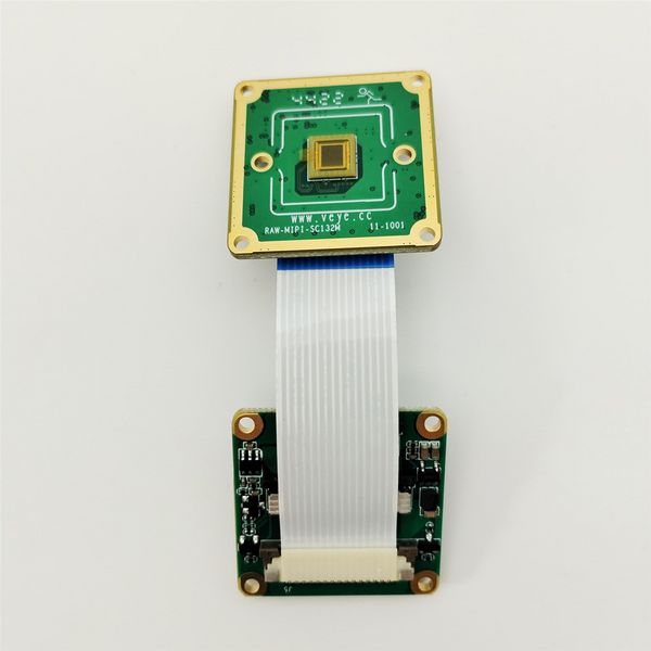
2.2 Connection of RAW-MIPI-SC132M and ADP-MV2
The two are connected using 1.0 mm pitch*15P FFC cable with opposite-side contacts. The cable must be inserted with the silver contacts facing outside.
| TOP
|
BOTTOM
|
 ADP-MV2 to RAW-MIPI-SC132M |
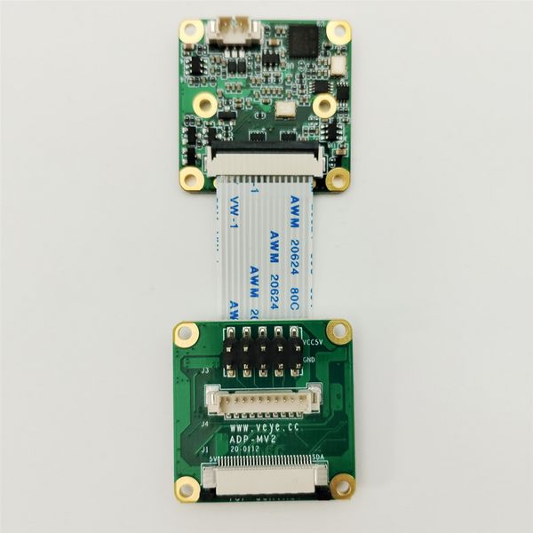 ADP-MV2 to RAW-MIPI-SC132M |
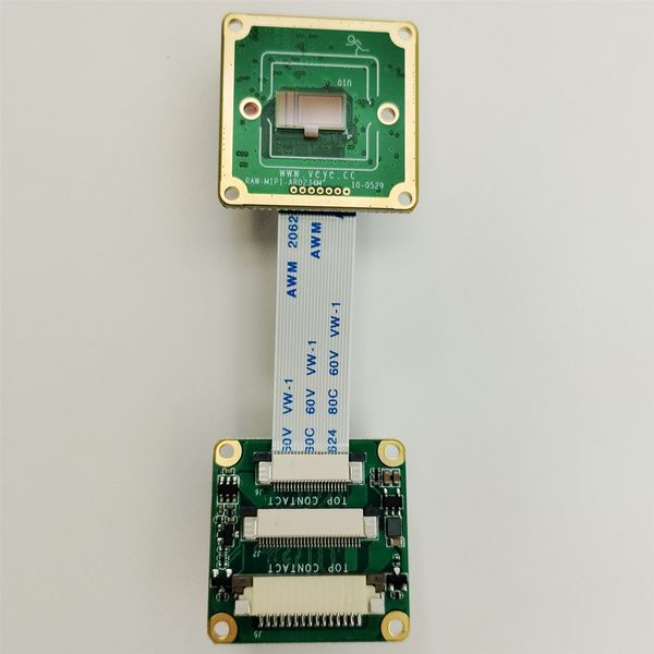
2.3 Connection of other RAW series camera and ADP-MV2
The two are connected using 0.5 mm pitch*pin FFC cable with opposite-side contacts. The cable must be inserted with the silver contacts facing outside.
| TOP
|
BOTTOM
|
 ADP-MV2 to RAW series camera |
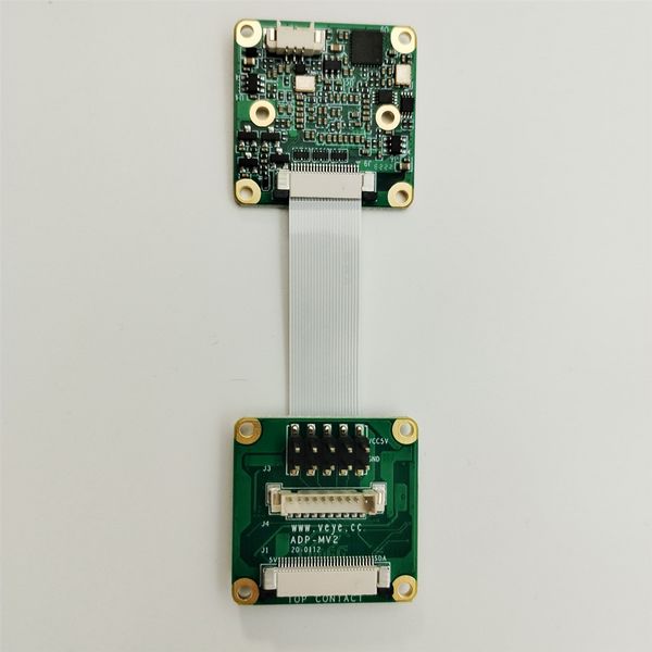 ADP-MV2 to RAW series camera |
2.4 Connection with Main board using ADP-MV2
The two are connected using 0.5mm pitch * 30P FFC coaxial wires, paying attention to the direction of the contact surfaces, silver contacts facing outside on the ADP-MV2 and facing inside on the RK board.
2.5 V-by-One-HS-KIT Camera Connection Diagram
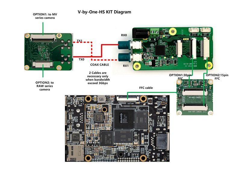
VBYONE connection with rk3588
3 Introduction to the GitHub Library
3.1 General part of the Rockchip platform
https://github.com/veyeimaging/rk35xx_veye_bsp
includes:
- driver source code
- i2c toolkits
- application demo
Domestic users can access the Gitee repository:
https://gitee.com/veyeimaging/rk35xx_veye_bsp
3.2 Firefly motherboard-related sections
https://github.com/veyeimaging/rk35xx_firefly
Including the following main contents:
- DTS source code and DTB files
- Driver compilation guidance document
Domestic users can access the Gitee repository:
https://gitee.com/veyeimaging/rk35xx_firefly
3.3 Board firmware image writing
In the GitHub releases, a pre-compiled Linux system image is provided.
Domestic users can download it through Baidu Cloud:https://pan.baidu.com/s/1LdK0n_uCx1yGej4PB8-bxg?pwd=yft9。
4 Upgrade Firefly Ubuntu system
For ROC-RK3566-PC, ROC-RK3576-PC and ROC-RK3588S-PC, we have provided the flashing images for the release system.
In the download path mentioned earlier, locate the corresponding image for the motherboard that supports the GX series camera products.
Refer to the Firefly documentation (ROC-RK3588S-PC ROC-RK3566-PC ROC-RK3576-PC) , and write the system.
5 Check system status
5.1 Whether the camera is correctly recognized
After completing the system installation and connecting the camera to the hardware, the system is powered on. Execute the following command on the Firefly board to check if the camera is connected correctly.
$ dmesg | grep gxcam
There should be similar prompts like the following:
[6.667547] gxcam 7-003b: veye gx series camera driver version: 01.00.01
[6.781681] gxcam 7-003b: camera is: GX-MIPI-IMX662
[6.820210] gxcam 7-003b: Success to get gxcam endpoint data lanes, dts uses 2 lanes,will set to camera
[6.834597] gxcam 7-003b: gxcam_enum_controls success
[6.891209] rockchip-csi2-dphy csi2-dphy0: dphy0 matches m00_b_gxcam 7-003b:bus type 5
By analyzing the above prompt information, it can be seen that the current camera model is GX-MIPI-IMX662.
From the 7-003b information, it can be seen that the current i2c bus number of the camera is 7 and the i2c address is 0x3b.
On ROC-RK3588S-PC, the camera is mounted on i2c-7; on ROC-RK3566-PC and ROC-RK3576-PC, the camera is mounted on i2c-4.
- Check the video0 device node:
ls /dev/video0
You should see:
video0
After correctly identifying the camera, the camera is recognized as /dev/video0.
At this point, the hardware installation of the camera and the driver installation have been completed. For subsequent application development, please refer to the following article.
6 Camera Application Development Guide
Application Development Guide
7 References
https://wiki.t-firefly.com/en/ROC-RK3566-PC/
https://wiki.t-firefly.com/en/ROC-RK3588S-PC/
https://wiki.t-firefly.com/en/ROC-RK3576-PC/
https://wiki.t-firefly.com/en/Firefly-Linux-Guide/index.html
8 Document History
The document format was adjusted and it was appropriately revised.
The first version.


