Mv series camera appnotes 4 rpi
1 Overview
The MV series cameras are cameras introduced for AI applications in the industrial field. It uses the MIPI CSI-2 interface, which is especially suitable for embedded computing platforms.
It features rich data formats and trigger characteristics, extremely low latency, extremely high bandwidth and reliable stability.
This article describes how to use the MV series camera on the Raspberry Pi platform.
1.1 Camera module list
| Series | Model | Status |
|---|---|---|
| MV series | MV-MIPI-IMX178M | Done |
| MV series | MV-MIPI-SC130M | Done |
| MV series | MV-MIPI-IMX296M | Done |
| MV series | MV-MIPI-IMX265M | Done |
| MV series | MV-MIPI-IMX264M | Done |
| RAW series | RAW-MIPI-SC132M | Done |
2 Hardware Setup
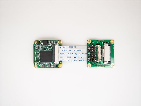
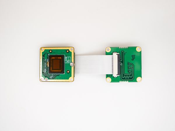
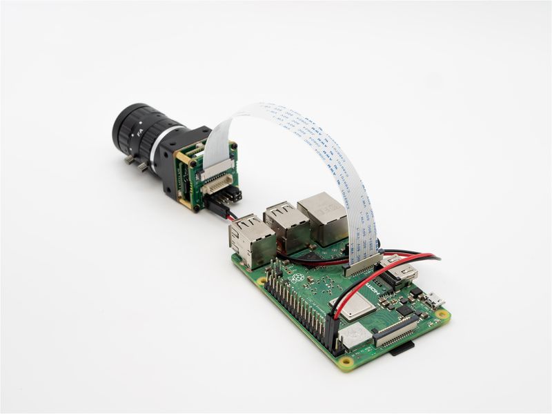
MV series cameras need to use ADP-MV1 adapter board in order to connect to Raspberry Pi.
We take MV-MIPI-IMX178M as an example to introduce the hardware installation method.
2.1 Connection of MV-MIPI-IMX178M and ADP-MV1
The two are connected using 0.5 mm pitch*30P FFC cable with opposite direction. The cable must be inserted with the silver contacts facing outside.
| TOP | BOTTOM |
|---|---|
2.2 Connection of ADP-MV1 to Raspberry Pi
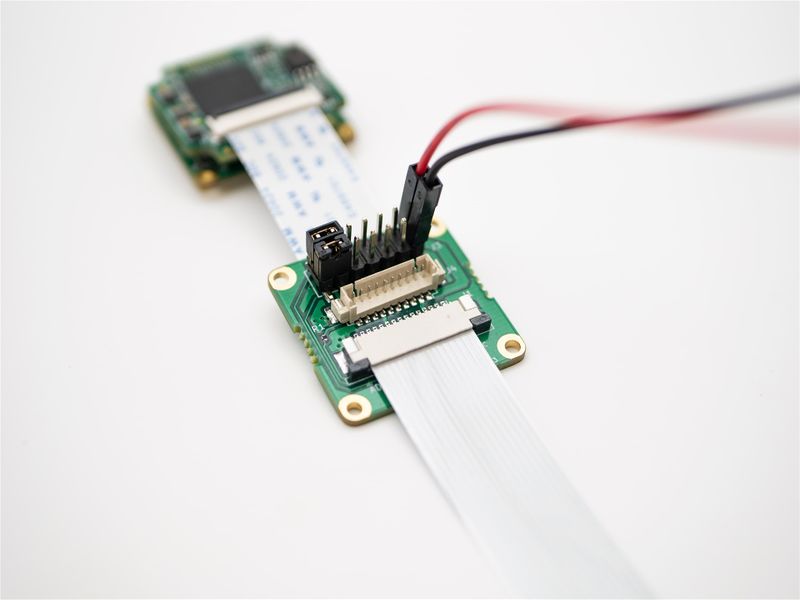
2.2.1 Power supply
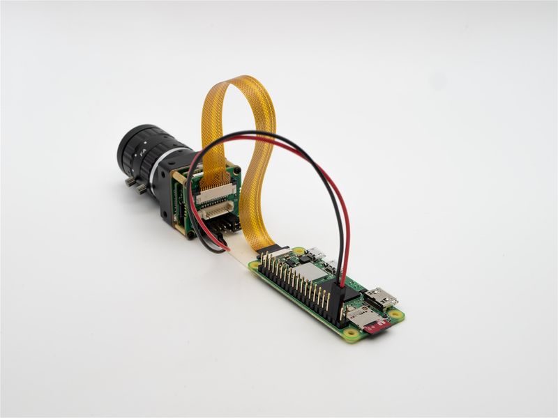
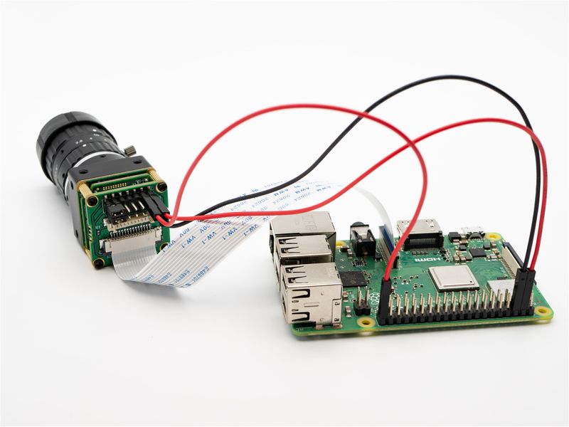
The ADP-MV1 requires a separate 5V power supply and can be powered directly from the Raspberry Pi motherboard using a Dupont cable.
2.2.2 Raspberry Pi Model B and B+
The two are connected using 1.0 mm pitch*15P FFC cable with opposite direction. Pay attention to the silver contacts facing side.
2.2.3 Raspberry Pi Zero, Zero W and Computer Module
The two are connected using 15Pto22P FFC cable with same direction. Pay attention to the silver contacts facing side.
3 piOS Configuration
For details on how to install the Raspberry Pi system, please refer to the official documentation at Install raspberry pi guide.
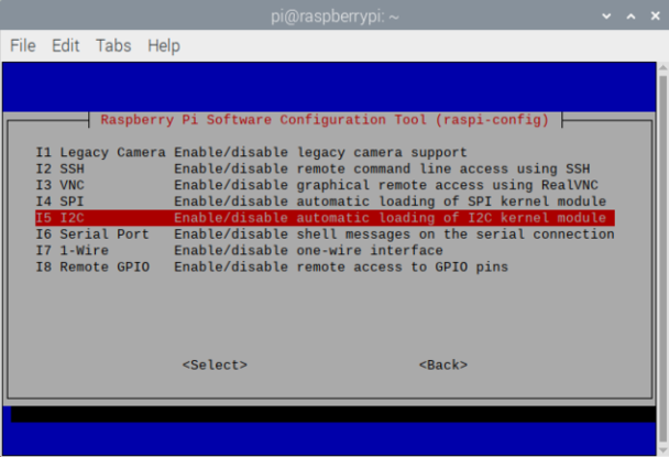
Initially, the Raspberry Pi system I2C is not enabled. After booting, we need to turn them on manually by executing the following command:
sudo raspi-config
Enter Interface Options, enable I2C, and then restart the Raspberry Pi.
It is recommended to enable the ssh service and samba service of Raspberry Pi system, here we will not go into the details of how to enable ssh and samba service of Raspberry Pi system.
4 Legacy mode and V4L2 mode introduction
The difference between these two modes is described in detail on the Raspberry Pi website. The libcamera-stack mode mentioned on the Raspberry Pi website is architecturally identical to the V4L2 mode we are talking about.
4.1 Legacy mode
Traditional mode, relying on Broadcom's GPU for image processing. The traditional raspicam software set uses this model.
The disadvantage of this model is closed. The GPU side is closed source, can not freely access sensor.
The Raspberry Pi organization has switched to the libcamera camera stack, but this model still has value:
- More use of GPU resources and lower CPU load. This is useful for earlier versions of the Raspberry Pi where CPU performance is poorer.
- It is possible to simply and directly fetch image data to the application layer without the support of the driver layer. This is especially useful for cameras that do not rely on the Raspberry Pi's isp.
- libcamera lacks some feature support now.
There are two ways to use Legacy mode.
- Use the Legacy version of piOS.
- For the bullseye or newer version of piOS, turn on the Legacy Camera option in raspi-config.
Since the two modes cannot co-exist, Legacy mode needs to be turned off when using V4L2 mode.
4.2 libcamera and V4L2 mode
Now piOS has switched to libcamera-stack mode.
Libcamera is essentially centered on implementing isp functionality, something that is not needed for the MV series cameras. Therefore, we have adopted the V4L2 mode instead of using libcamera-stack.
As with libcamera-stack, our V4L2 model implements the standard V4L2 driver for the linux driver layer too. Based on this driver, the application layer can directly develop programs to acquire images and perform further processing.
5 Configuring global variables
For the convenience of later descriptions, global variables are configured here according to the sensor size.
- MV-MIPI-IMX178M
export WIDTH=3088
export HEIGHT=2064
export FPS=22
- MV-MIPI-SC130M
export WIDTH=1280
export HEIGHT=1024
export FPS=108
- MV-MIPI-IMX296M
export WIDTH=1440
export HEIGHT=1088
export FPS=60
- MV-MIPI-IMX265M
export WIDTH=2048
export HEIGHT=1544
export FPS=45
- MV-MIPI-IMX264M
export WIDTH=2432
export HEIGHT=2056
export FPS=28
- RAW-MIPI-SC132M
export WIDTH=1080
export HEIGHT=1280
export FPS=120
6 V4L2 mode manual
We have saved the code for v4l2 mode in this github repository.
6.1 Download the driver package
wget https://github.com/veyeimaging/raspberrypi_v4l2/releases/latest/download/raspberrypi_v4l2.tgz
6.2 Install driver
tar -xzvf raspberrypi_v4l2.tgz
cd raspberrypi_v4l2/release/
chmod +x *
sudo ./install_driver.sh veye_mvcam
Then reboot Raspberry Pi.
Note: If you are prompted that the corresponding version of the driver cannot be found, it means that we do not provide a compiled driver corresponding to your piOS version. Please try to compile from the source code.
6.3 Uninstall the driver
If you need to change to Legacy mode, or want to change to another camera module model driver, you must uninstall the current driver first.
sudo ./uninstall_driver.sh veye_mvcam
6.4 Check system status
Take MV-MIPI-IMX178M as an example.
dmesg | grep mvcam
You can see the camera model and the version of the camera probed during the Linux boot phase.
camera is: MV-MIPI-IMX178M
firmware version: 0x1080102
And the /dev/video0 node exists, which proves that the camera status is normal.
6.5 v4l2-ctl application examples
6.5.1 Install v4l2-utils
sudo apt-get install v4l-utils
6.5.2 Install yavta
git clone git://git.ideasonboard.org/yavta.git
cd yavta;make
6.5.3 Configure parameters using v4l2-ctl
6.5.3.1 List the data formats supported by the camera
v4l2-ctl --list-formats-ext
ioctl: VIDIOC_ENUM_FMT
Type: Video Capture
[0]: 'GREY' (8-bit Greyscale)
Size: Discrete 3088x2064
[1]: 'Y10P' (10-bit Greyscale (MIPI Packed))
Size: Discrete 3088x2064
[2]: 'Y10 ' (10-bit Greyscale)
Size: Discrete 3088x2064
[3]: 'Y12P' (12-bit Greyscale (MIPI Packed))
Size: Discrete 3088x2064
[4]: 'Y12 ' (12-bit Greyscale)
Size: Discrete 3088x2064
[5]: 'UYVY' (UYVY 4:2:2)
Size: Discrete 3088x2064
Note: UYVY data format is for debugging use only.
6.5.3.2 List the configurable parameters of the camera implemented in the driver
v4l2-ctl -L
User Controls
horizontal_flip 0x00980914 (bool) : default=0 value=0
vertical_flip 0x00980915 (bool) : default=0 value=0
trigger_mode 0x00981901 (int) : min=0 max=2 step=1 default=0 value=0 flags=volatile
trigger_src 0x00981902 (int) : min=0 max=1 step=1 default=1 value=1 flags=volatile
soft_trgone 0x00981903 (button) : flags=write-only, execute-on-write
frame_rate 0x00981904 (int) : min=0 max=22 step=1 default=22 value=22 flags=volatile
Parameters can be set and get using the following methods.
v4l2-ctl --set-ctrl [ctrl_type]=[val]
v4l2-ctl --get-ctrl [ctrl_type]
All the above functions can be implemented using mv_mipi_i2c.sh.
None of the above parameters can be modified in the state when the image acquisition is started.
Each of them is described below:
6.5.3.3 horizontal and vertical flip
- horizontal flip
v4l2-ctl --set-ctrl horizontal_flip=1
- vertical flip
v4l2-ctl --set-ctrl vertical_flip=1
6.5.3.4 Trigger Mode
v4l2-ctl --set-ctrl trigger_mode=[0-2]
0:Video streaming mode
1:Normal trigger mode.
2:High-speed continuous trigger mode.
6.5.3.5 Trigger Source
v4l2-ctl --set-ctrl trigger_src=[0-1]
0: Software trigger mode.
1: Hardware trigger mode.
6.5.3.6 Software trigger command
v4l2-ctl --set-ctrl soft_trgone=1
6.5.3.7 Set frame rate
v4l2-ctl --set-ctrl frame_rate=[1-max]
The maximum frame rate is automatically updated as the resolution changed.
6.5.3.8 Set ROI
For example:
- MV-MIPI-IMX178M
v4l2-ctl --set-selection=target=crop,top=32,left=64,width=2592,height=1944
- MV-MIPI-SC130M
v4l2-ctl --set-selection=target=crop,top=32,left=64,width=640,height=640
The maximum frame rate will be adjusted automatically after setting ROI.
6.6 Video Streaming mode
6.6.1 Set ROI
v4l2-ctl --set-selection=target=crop,top=0,left=0,width=$WIDTH,height=$HEIGHT
6.6.2 Set Framerate
v4l2-ctl --set-ctrl frame_rate=$FPS
6.6.3 Frame rate statistics
In streaming mode, the following commands can be used for frame rate statistics.
v4l2-ctl --set-fmt-video=width=$WIDTH,height=$HEIGHT,pixelformat=GREY --stream-mmap --stream-count=-1 --stream-to=/dev/null
6.6.4 Save image to file
6.6.4.1 MV-MIPI-IMX178M
- raw8
v4l2-ctl -d /dev/video0 --set-fmt-video=width=3088,height=2064,pixelformat=GREY --stream-mmap --stream-count=1 --stream-to=y8-3104x2064.raw
Or
./yavta -c1 -Fy8-3104x2064.raw --skip 0 -f Y8 -s 3088x2064 /dev/video0
Since the memory requested by Raspberry Pi for the image, the width is 32-align and the height is 16-align, the 3088*2064 image will be saved as 3104*2064 size.
- raw10
v4l2-ctl -d /dev/video0 --set-fmt-video=width=3088,height=2064,pixelformat='Y10 ' --stream-mmap --stream-count=1 --stream-to=y10-3088x2064.raw
- raw12
v4l2-ctl -d /dev/video0 --set-fmt-video=width=3088,height=2064,pixelformat='Y12 ' --stream-mmap --stream-count=1 --stream-to=y12-3088x2064.raw
6.6.4.2 MV-MIPI-SC130M
- raw8
v4l2-ctl -d /dev/video0 --set-fmt-video=width=1280,height=1024,pixelformat=GREY --stream-mmap --stream-count=1 --stream-to=y8-1280x1024.raw
- raw10
v4l2-ctl -d /dev/video0 --set-fmt-video=width=1280,height=1024,pixelformat='Y10 ' --stream-mmap --stream-count=1 --stream-to=y10-1280x1024.raw
6.6.4.3 MV-MIPI-IMX296M
- raw8
v4l2-ctl -d /dev/video0 --set-fmt-video=width=1440,height=1088,pixelformat=GREY --stream-mmap --stream-count=1 --stream-to=y8-1440x1088.raw
- raw10
v4l2-ctl -d /dev/video0 --set-fmt-video=width=1440,height=1088,pixelformat='Y10 ' --stream-mmap --stream-count=1 --stream-to=y10-1440x1088.raw
6.6.4.4 MV-MIPI-IMX265M
- raw8
v4l2-ctl -d /dev/video0 --set-fmt-video=width=2048,height=1544,pixelformat=GREY --stream-mmap --stream-count=1 --stream-to=y8-2048x1544.raw
- raw10
v4l2-ctl -d /dev/video0 --set-fmt-video=width=2048,height=1544,pixelformat='Y10 ' --stream-mmap --stream-count=1 --stream-to=y10-2048x1544.raw
- raw12
v4l2-ctl -d /dev/video0 --set-fmt-video=width=2048,height=1544,pixelformat='Y12 ' --stream-mmap --stream-count=1 --stream-to=y12-2048x1544.raw
6.6.4.5 MV-MIPI-IMX264M
- raw8
v4l2-ctl -d /dev/video0 --set-fmt-video=width=2432,height=2056,pixelformat=GREY --stream-mmap --stream-count=1 --stream-to=y8-2432x2056.raw
- raw10
v4l2-ctl -d /dev/video0 --set-fmt-video=width=2432,height=2056,pixelformat='Y10 ' --stream-mmap --stream-count=1 --stream-to=y10-2432x2056.raw
- raw12
v4l2-ctl -d /dev/video0 --set-fmt-video=width=2432,height=2056,pixelformat='Y12 ' --stream-mmap --stream-count=1 --stream-to=y12-2432x2056.raw
6.6.4.6 RAW-MIPI-SC132M
- raw8
v4l2-ctl -d /dev/video0 --set-fmt-video=width=1080,height=1280,pixelformat=GREY --stream-mmap --stream-count=1 --stream-to=y8-1088x1280.raw
- raw10
v4l2-ctl -d /dev/video0 --set-fmt-video=width=1080,height=1280,pixelformat='Y10 ' --stream-mmap --stream-count=1 --stream-to=y10-1088x1280.raw
PS. This y8 file can be used with this player: YUV Displayer Deluxe.
6.7 Trigger mode
This section takes IMX178 as an example to show the configuration and use of trigger mode. For other cameras, just refer to the width and height of the stream mode.
6.7.1 Set ROI and Framerate
v4l2-ctl --set-selection=target=crop,top=0,left=0,width=$WIDTH,height=$HEIGHT
v4l2-ctl --set-ctrl frame_rate=$FPS
6.7.2 Software trigger mode
6.7.2.1 Set mode
v4l2-ctl --set-ctrl trigger_mode=1
v4l2-ctl --set-ctrl trigger_src=0
6.7.2.2 Start acquisition
v4l2-ctl --set-fmt-video=width=3088,height=2064,pixelformat=GREY --stream-mmap --stream-count=5 --stream-to=y8-3104x2064.yuv
6.7.2.3 Perform soft trigger operation
In other shell terminals, you can execute the following command multiple times for multiple triggers.
v4l2-ctl --set-ctrl soft_trgone=1
6.7.3 Hardware trigger mode
The following is an example of using Raspberry Pi GPIO21 as an trigger source with rising edge trigger.
You can use the mv_mipi_i2c.sh script for other trigger parameter setting.
6.7.3.1 Hardware Connection
6.7.3.2 Set mode
v4l2-ctl --set-ctrl trigger_mode=1
v4l2-ctl --set-ctrl trigger_src=1
6.7.3.3 Start acquisition
v4l2-ctl --set-fmt-video=width=3088,height=2064,pixelformat=GREY --stream-mmap --stream-count=5 --stream-to=y8-3104x2064.yuv
6.7.3.4 Perform hardware trigger operation
python gpio_trigger.py
Note: script link.
6.8 Notes for CM4
Cm4 supports the use of two cameras at the same time. Following above steps will only be able to use CAM1. To use two cameras, follow the following steps:
6.8.1 Upgrade dt-blob.bin
sudo wget https://datasheets.raspberrypi.com/cmio/dt-blob-dualcam.bin -O /boot/dt-blob.bin
6.8.2 Upgrade dual camera version dtbo file
Use mvcam as an example:
sudo cp raspberrypi_v4l2/release/driver_bin/$(uname -r)/veye_mvcam-cm4.dtbo /boot/overlays/veye_mvcam.dtbo
sudo reboot
6.8.3 Device node description
The CM4 module uses two I2C channels to communicate with the two cameras respectively.
| description | i2c bus num | video node |
|---|---|---|
| CAM0 | 0 | video0 |
| CAM1 | 10 | video2 |
Note: If there is only one camera, video node is always video0.
6.9 Compiling drivers from source code
Please refer to: Build drivers from source for rpi.
7 Legacy mode manual
We store the code for legacy patterns in this github repository.
7.1 Download the software package
git clone https://github.com/veyeimaging/mvcam_raspberrypi.git
Add executable permissions:
chmod +x -R ./mvcam_raspberrypi/
7.2 Software package main content introduction
camera_i2c_config:Automatically recognizes different Raspberry Pi board types and controls the power on pins to power the camera.
mv_raspicam:Realize image preview, image saving and other functions.
mv_mipi_i2c.sh:Scripts for reading and setting camera parameters via i2c protocol.
veye_i2c_upgrade:Camera firmware upgrade tool.
7.3 Camera power on
./camera_i2c_config
When the camera is powered on, try:
i2cdetect -y 10
The presence of a 0x3b device indicates that the camera is on and the i2c channel is working properly.
7.4 Preview
./mv_raspicam -t -1 -roi 0,0,3088,2064 -md 0
where -md specifies the pixel data format.
| -md option | data type |
|---|---|
| 0 | 8bit Y |
| 1 | 10bit Y |
| 2 | 12bit Y |
-roi specifies the desired ROI size.
For sizes larger than 1920 in width, mv_raspicam will first reduce to half the original size of the image and then send to render.
7.5 Save image
./mv_raspicam -t 1000 -roi 0,0,3088,2064 -md 0 -sr 10 -o /dev/shm/y8-3104x2064_%04d.yuv
-sr is the interval for storing images, one image is saved every 10 images here.
-t 1000, in ms, it means 1 second here.
Several files will be saved in the /dev/shm/ directory after completion.
7.6 Trigger mode
This section requires the use of mv_mipi_i2c.sh, please refer to the related i2c parameter configuration section below.
7.6.1 Software trigger mode
7.6.1.1 Set mode
./mv_mipi_i2c.sh -w -f trgmode -p1 1
./mv_mipi_i2c.sh -w -f trgsrc -p1 0
7.6.1.2 Set trigger properties
You can set the number of triggers, trigger interval, etc.
The following settings are for a single trigger of 5 images with an interval of 1 second each.
./mv_mipi_i2c.sh -w -f trgnum -p1 5
./mv_mipi_i2c.sh -w -f trginterval -p1 1000
7.6.1.3 Start acquisition
./mv_raspicam -t -1 -roi 0,0,3088,2064 -md 0
7.6.1.4 Perform soft trigger operation
In other shell terminals, you can execute the following command multiple times for multiple triggers.
./mv_mipi_i2c.sh -w -f trgone
7.6.2 Hardware trigger mode
The following is an example of using Raspberry Pi GPIO21 as an trigger source with rising edge trigger.
You can use the mv_mipi_i2c.sh script for other trigger parameter setting.
7.6.2.1 Hardware Connection
7.6.2.2 Set mode
This time, we use high-speed continuous trigger as an example.
./mv_mipi_i2c.sh -w -f trgmode -p1 2
./mv_mipi_i2c.sh -w -f trgsrc -p1 1
7.6.2.3 Set trigger properties
The trigger interval is invalid under high-speed continuous triggering. This time trigger 2 images.
./mv_mipi_i2c.sh -w -f trgnum -p1 2
Set rising edge trigger
./mv_mipi_i2c.sh -w -f trgedge -p1
In addition, rich trigger attributes can be set for hard triggering, such as trigger delay, signal filtering, etc.
7.6.2.4 Start acquisition
./mv_raspicam -t -1 -roi 0,0,3088,2064 -md 0
7.6.2.5 Perform hardware trigger operation
python gpio_trigger.py
Note: script link.
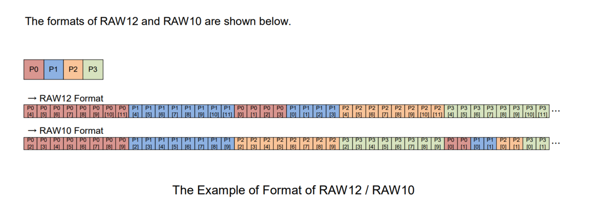
7.7 Raw data picture format
7.8 Unpacked image format(padded)
For 10bit depth and 12bit depth pixel data, two bytes are always used to store one pixel. The V4L2 standard 'Y10 ' (10-bit Greyscale),'Y12 ' (12-bit Greyscale)formats are stored in this way.
This storage method is convenient for software processing, but has the disadvantage of taking up more space.
7.9 Packed image format
The data format saved by mv_raspicam is the data format on the MIPS bus, with no empty bit padding between pixels.
The V4L2 standard'Y10P' (10-bit Greyscale (MIPI Packed)),'Y12P' (12-bit Greyscale (MIPI Packed))formats are stored in this way.
7.10 Packed image size
Buffersize= ALIGN_UP(width*bit_depth/8,32)*ALIGN_UP(height,16)
The row buffer size should be 32 bytes aligned; the column buffer size should be 16 bytes aligned.
For example, the image size of 3088*2064@8bit is 6406656; the image size of 3088*2064@10bit is 7991808; the image size of 3088*2064@12bit is 9576960.
7.11 Format convert tool
We have written a small tool: pixel_layer_convert, which can easily convert packed images to unpacked images.
For example, the following command converts a packed raw10 image of 3088 width to an unpacked raw10.
./pixel_layer_convert -I Y10P -i y10-3088x2064_0001.raw -o y10-3088x2064_0001_new.raw -w 3088
7.12 Raw data image player
We recommend using vooya as the player, which supports GREY, and unpacked image formats.
Also, y8 file can be used with this player: YUV Displayer Deluxe.
Since the memory requested by Raspberry Pi for the image, the width is 32-align and the height is 16-align, the 3088*2064 image will be saved as 3104*2064 size.
8 i2c script for parameter configuration
We provide shell scripts to configure the parameters.
9 References
- Installation of the Raspberry Pi system
- The difference between Raspberry Pi legacy camera stack and libcamera mode
10 Document History
- 2023-02-10
Add note for CM4.
- 2022-12-08
Add support for the new VEYE-MIPI-IMX264M camera model.
- 2022-11-02
Add support for the new IMX265 and SC132 models.
- 2022-05-16
Provide image format convert tool.
- 2022-04-14
Release 1st version.
